
Multi-eye camera and method for distinguishing three-dimensional object

a three-dimensional object and camera technology, applied in the field of multi-eye cameras, can solve the problems of upsizing, cost increase, subject hard to see, etc., and achieve the effect of cost increas

Inactive Publication Date: 2011-04-21
FUJIFILM CORP
View PDF6 Cites 19 Cited by
  • Summary
  • Abstract
  • Description
  • Claims
  • Application Information

AI Technical Summary

Benefits of technology

[0010]A main object of the present invention is to provide a multi-eye camera that can appropriately distinguish whether a subject is a three-dimensional object or a printed sheet even if the printed sheet contains a shadow, and a method for appropriately distinguishing the subject.
[0011]Another object of the present invention is to provide the multi-eye camera that is small in size and inexpensive, and the distinction method that does not require upsizing and cost increase of the camera.
[0021]According to the present invention, the shadow of the same subject is extracted from each of the plural viewpoint images captured in the preliminary photographing procedure. If the difference in size of the shadow between the viewpoint images is the predetermined size difference threshold value or more, the subject is distinguished as the three-dimensional object suited to the 3D picture mode. If the difference in size of the shadow between the viewpoint images is less than the size difference threshold value, the subject is distinguished as the printed sheet suited to the 2D picture mode. Thus, eve if the printed sheet contains the shadow, it is possible to precisely distinguish the subject between the three-dimensional object and the printed sheet, and choose the appropriate photographing mode. Since the multi-eye camera does not require various sensors and an analyzing device to conduct complex analysis, the multi-eye camera is realized without upsizing and cost increase.

Problems solved by technology

If anything, binocular disparity causes the subject hard to see.
This method, however, needs various sensors to obtain the photographing information, a shadow analyzing device, and the like, and results in upsizing and cost increase of the multi-eye camera.

Method used


Image

  • Multi-eye camera and method for distinguishing three-dimensional object
  • Multi-eye camera and method for distinguishing three-dimensional object
  • Multi-eye camera and method for distinguishing three-dimensional object

Examples


first embodiment

[0085]After calculation of the scaling rate P, the horizontal scaling section 104 stretches or shrinks the shadow of the R viewpoint image at that scaling rate P. The horizontal scaling section 104 then inputs to the size calculating section 86 the processed shadow data of the R viewpoint image and the unprocessed shadow data of the L viewpoint image. The size calculating section 86, as in the case of the first embodiment, calculates the size of the shadow of the main subject in each of the processed R viewpoint image and the unprocessed L viewpoint image based on the shadow data inputted from the horizontal scaling section 104, and inputs calculation results to the difference calculating section 87.

second embodiment

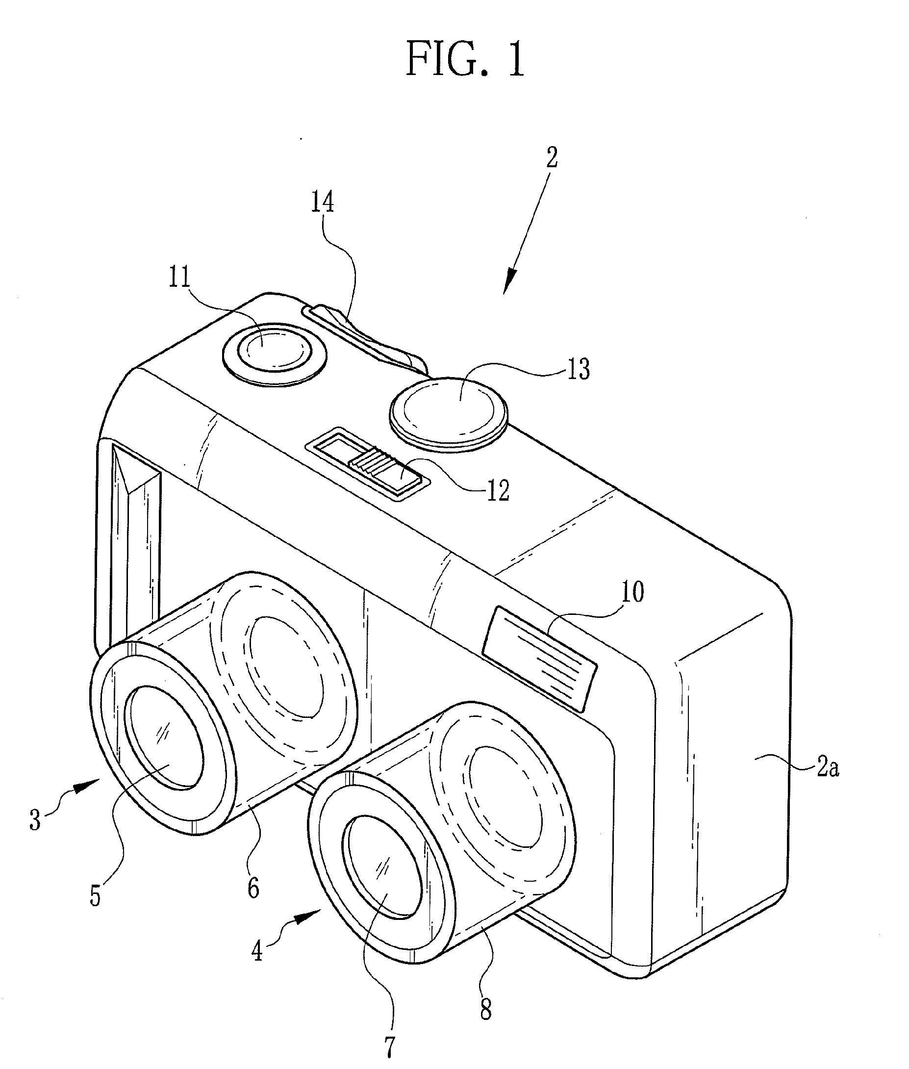
[0086]Next, operation of the stereo camera 100 will be described with referring to a flowchart of FIG. 9. When the stereo camera 100 is put into the automatic switching mode and the shutter release button 11 is half pressed, the preliminary photographing procedure is started. The AE processing and the multipoint AF processing are carried out, in order to adjust the exposure amount and the white balance of each imaging unit 3, 4 and adjust the focus of each imaging optical system 5, 7. Simultaneously, the binary image generator 84 applies the binary processing to each viewpoint image, and the binary R and L viewpoint images are inputted to the shadow extracting section 85.

[0087]The shadow extracting section 85 extracts the shadow of the main subject from each of the inputted binary R and L viewpoint images. The extracted shadow data is inputted to the size calculating section 86 and the horizontal scaling section 104. If the shadow is not extracted, on the other hand, the shadow ext...

third embodiment

[0102]Now, operation of the stereo camera 110 will be described with referring to a flowchart of FIG. 12. When the stereo camera 110 is put into the automatic switching mode and the shutter release button 11 is half pressed, the AE processing and the multipoint AF processing are carried out in response to the half press of the shutter release button 11, to adjust the exposure amount and the white balance of each imaging unit 3, 4 and bring each imaging optical system 5, 7 into focus. At the same time, the binary image generator 84 applies the binary processing to each of the R and L viewpoint images, and the binary R and L viewpoint images are inputted to the shadow extracting section 85.

[0103]The shadow extracting section 85 applies the shadow extracting processing to each of the inputted binary R and L viewpoint images, in order to extract the shadow of the main subject. If the shadow is proper extracted, the shadow data is inputted to the size calculating section 86. If the shad...


PUM


Abstract

A stereo camera captures a pair of R and L viewpoint images. Upon a half press of a shutter release button, a preliminary photographing procedure is carried out. A binary image generator applies binary processing to each image, and a shadow extracting section extracts a shadow of a main subject from each binary image. A size calculating section calculates a size of each shadow, and a difference calculating section calculates a difference in size of the shadow between the images. If an absolute value of the difference is a size difference threshold value or more, the main subject is distinguished as a three-dimensional object suited to a 3D picture mode. Otherwise, the main subject is distinguished as a printed sheet suited to a 2D picture mode. Upon a full press of the shutter release button, an actual photographing procedure is carried out in the established 3D or 2D picture mode.

Description

BACKGROUND OF THE INVENTION[0001]1. Field of the Invention[0002]The present invention relates to a multi-eye camera that takes a plurality of viewpoint images with use of a plurality of imaging optical systems, and a method for distinguishing based on the viewpoint images whether or not a subject is a three-dimensional object.[0003]2. Description Related to the Prior Art[0004]A multi-eye camera that obtains a parallax image to get a three-dimensional view is widely known. The parallax image is a collection of two-dimensional viewpoint images. The conventional multi-eye camera is provided with a plurality of imaging optical systems to obtain the plural viewpoint images. In reproduction, these viewpoint images are merged to generate the parallax image.[0005]Most of the multi-eye cameras are switchable between a 2D picture mode for obtainment of a single 2D image and a 3D picture mode for obtainment of the parallax image. This is because if a subject is a planar printed sheet such as a...

Claims


Application Information

Patent Timeline
IPC IPC(8): H04N13/02G06K9/00G06T7/593
CPCG06T7/0053H04N13/0239G06T2207/10012G06T7/0075G06T7/507G06T7/593H04N13/239
Inventor TSUCHITA, AKIYOSHI
Owner FUJIFILM CORP
Learn More