

Stereovision system and method for calcualting distance between object and diffractive optical element
- Summary
- Abstract
- Description
- Claims
- Application Information
AI Technical Summary
Benefits of technology
Problems solved by technology
Method used
Image

Examples
Embodiment Construction
[0020]For your esteemed members of reviewing committee to further understand and recognize the fulfilled functions and structural characteristics of the disclosure, several exemplary embodiments cooperating with detailed description are presented as the follows.
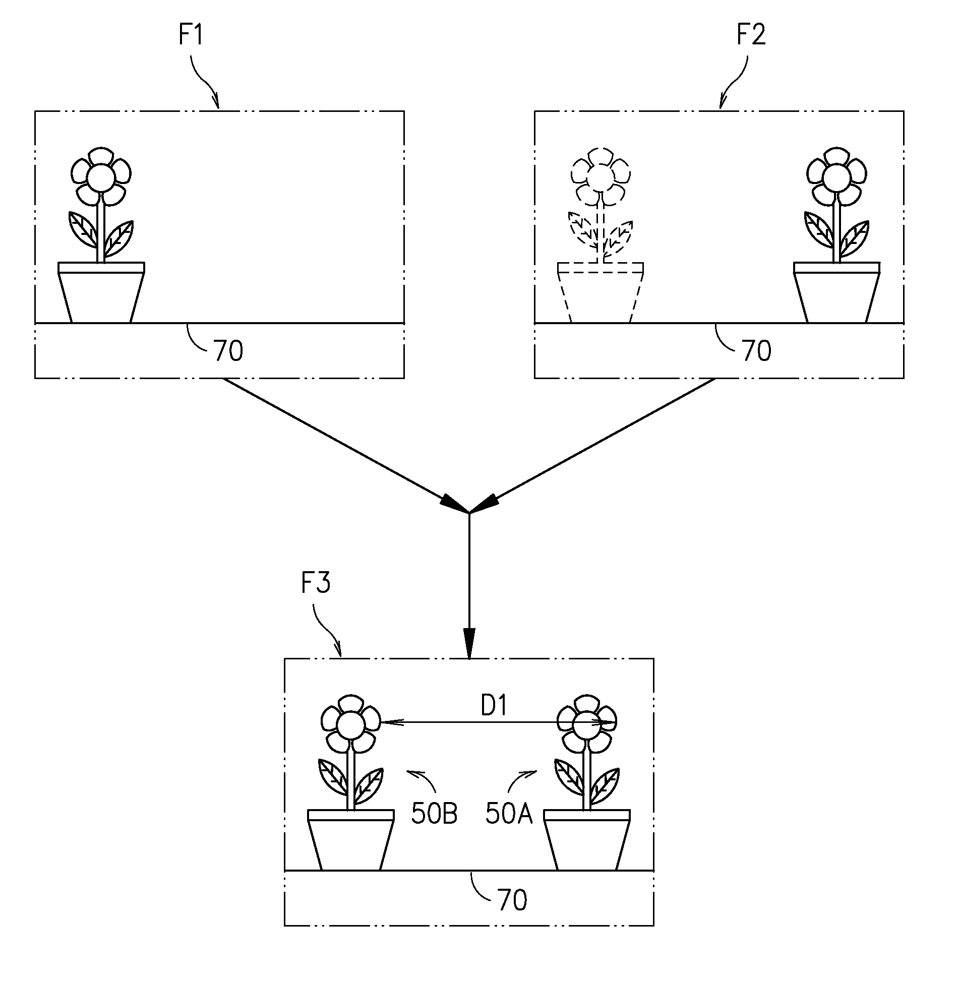
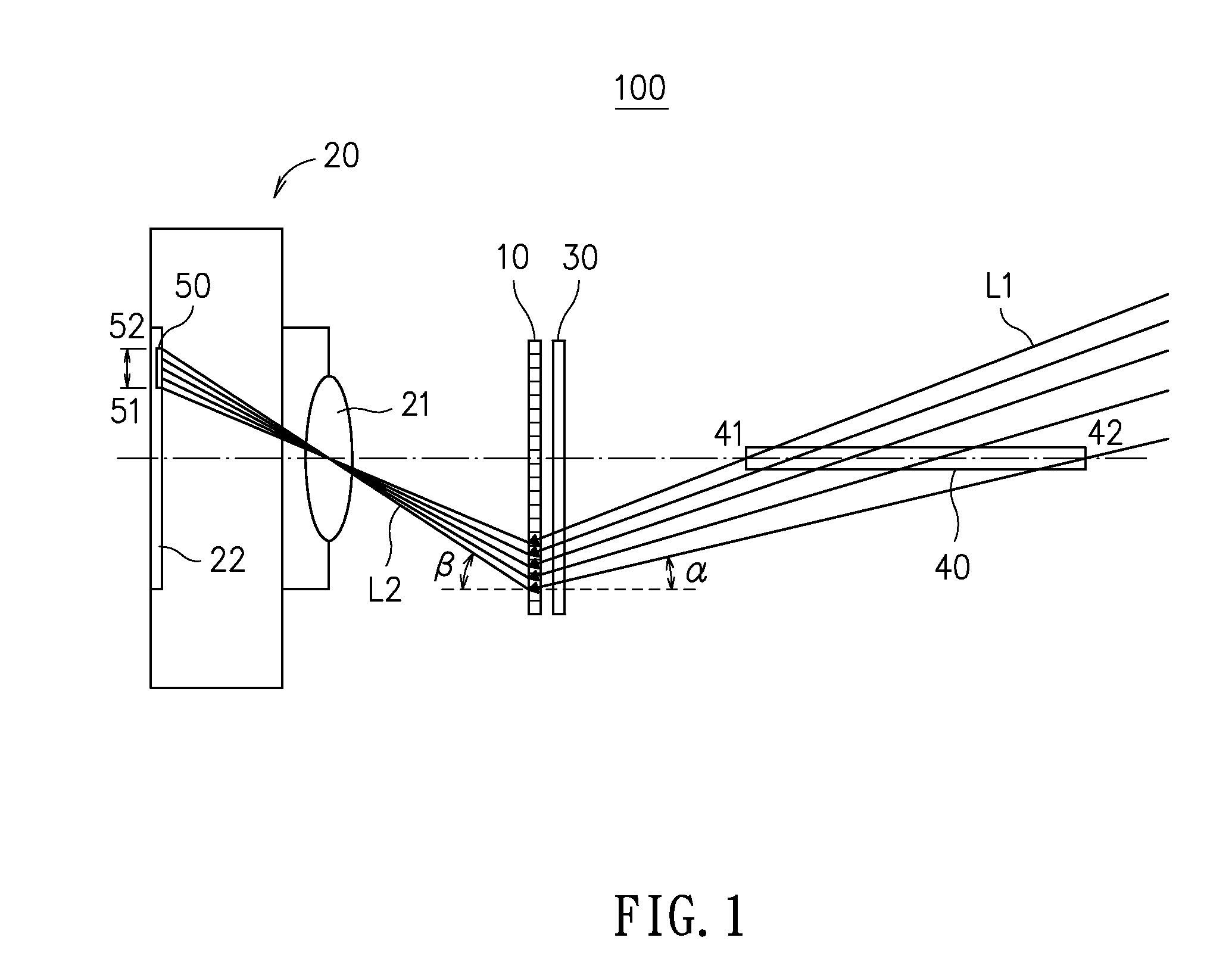
[0021]Please refer to FIG. 1, which is a schematic diagram showing a stereovision system according to an embodiment of the present disclosure. In FIG. 1, a stereovision system 100 is disclosed, which is comprised of: a diffractive optical element 10 and an optical imaging device 20. The diffractive optical element 10 can be a transmission blazed grating as it is characterized in that: it can change the traveling direction of an incident light for concentrating energy to a specific order of diffraction and thus enhance the image resulting from that order of diffraction while simultaneously enabling the other orders of diffraction with lower energy concentration to form images. As shown in FIG. 1, a first beam L1 is provided fo...
PUM
 Abstract
Description
Claims
Application Information