Electrical power supply device comprising a tray for accommodating ultra-high capacity storage units

a technology for electric power supply devices and storage units, which is applied in the direction of cell components, fixed capacitors, cell component details, etc., can solve the problems of unnecessary expense, short service life of storage units in comparison with other storage units, and many problems of supply devices, so as to reduce the number of parts, simple and economical

Active Publication Date: 2011-04-21
VALEO EQUIP ELECTRIC MOTEUR
View PDF15 Cites 39 Cited by
  • Summary
  • Abstract
  • Description
  • Claims
  • Application Information

AI Technical Summary

Benefits of technology

The solution according to the invention thus makes it possible to decrease the number of parts, and is therefore simple and economical.

Problems solved by technology

However, these electrical supply devices pose many problems.
This storage unit therefore has a short service life in comparison with the other storage units.
This therefore gives rise to unnecessary expense.

Method used


Image

  • Electrical power supply device comprising a tray for accommodating ultra-high capacity storage units
  • Electrical power supply device comprising a tray for accommodating ultra-high capacity storage units
  • Electrical power supply device comprising a tray for accommodating ultra-high capacity storage units

Examples


fourth embodiment

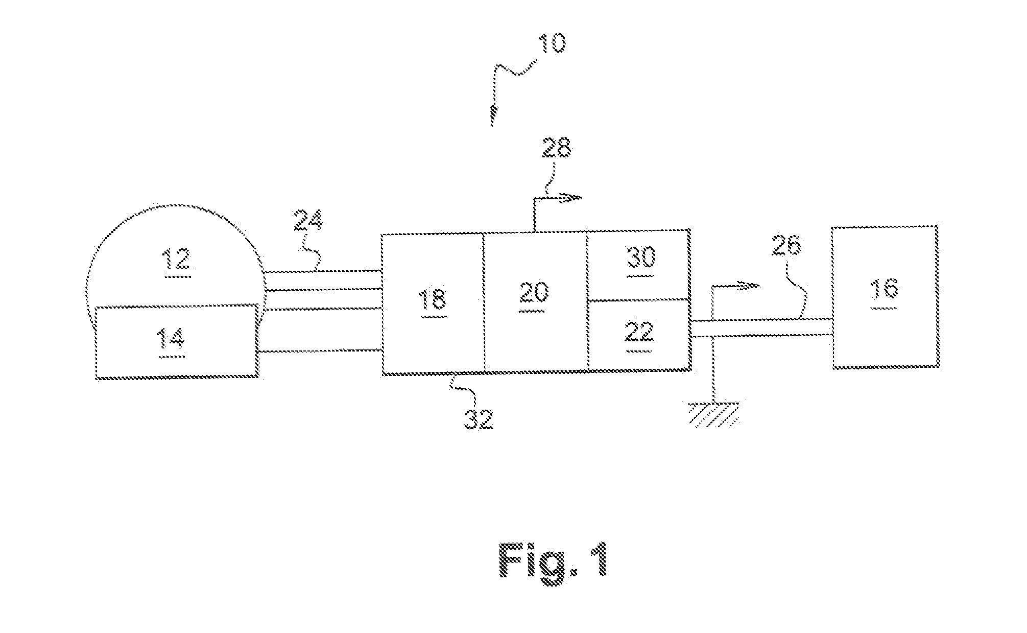
in the non-limiting example which is shown in FIG. 1, the device 10 comprises three electronic converters, i.e. an inverter 18, a direct / direct converter 22, and in addition a two-position switch 30 or two switches 30, which are connected to one another by means of power connections such as bus bars (not shown).

In the above-described manner, the inverter 18 is a so-called AC / DC reversible alternating / direct current electric converter in electric generator mode, or a so-called DC / AC direct / alternating converter in electric motor mode.

The direct / direct converter 22 makes it possible in particular to convert a voltage on the energy storage unit side 20, the said voltage being situated in a range of values, in this case in a non-limiting manner, between 6 V and 35 V, into a voltage which is compatible with that of the battery 16, the battery supplying an on-board network of, for example, approximately 12 Volts.

The two-position switch 30 or the two switches 30, for their part make it pos...

second embodiment

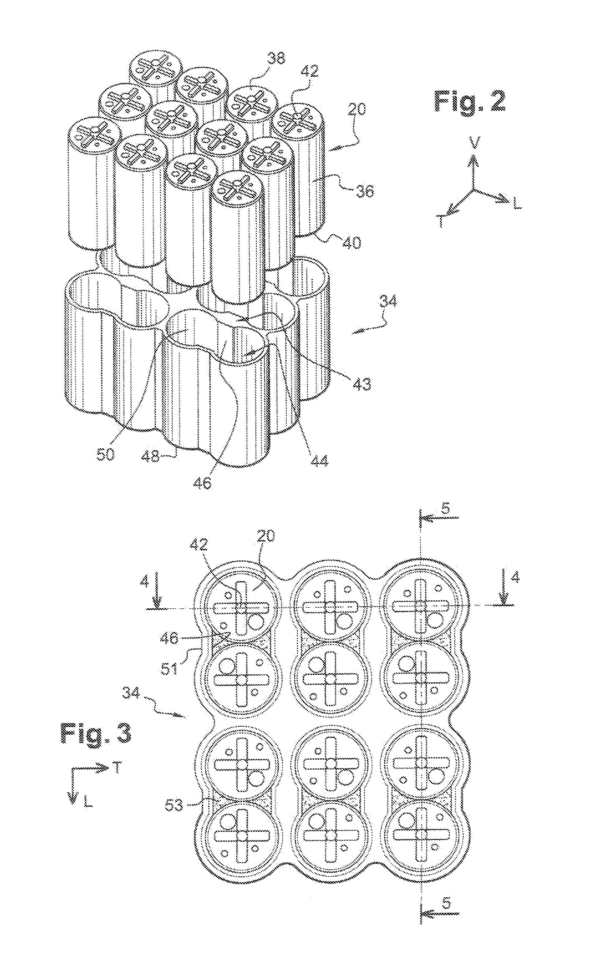
The glue 56 also makes it possible to reduce the quantity of resin 54. In fact, in FIGS. 4 and 5, the resin extends along the entire height of the receptacle 44. As a variant, by means of the glue 56, the resin can extend along less than 80% of the vertical height of the receptacle, for example over 50% of the height of the receptacle 44. The same applies in the second embodiment in FIGS. 6 and 7. It will be appreciated that the shape of the receptacle 44, which is globally in the form of an “8”, makes it possible to reduce the quantity and therefore the volume of heat-conducting resin 54 used.

As a variant, the layer 54 of heat-conducting resin is replaced by glue of the same type as the glue 56.

As a variant, the layers 54 and 56 are produced by means of a heat-conducting resin which has adhesive properties.

Once it has hardened, this resin becomes adhesive.

In the aforementioned manner, a resin has been selected which, once it has hardened, has properties of adhesion, flexibility and...

third embodiment

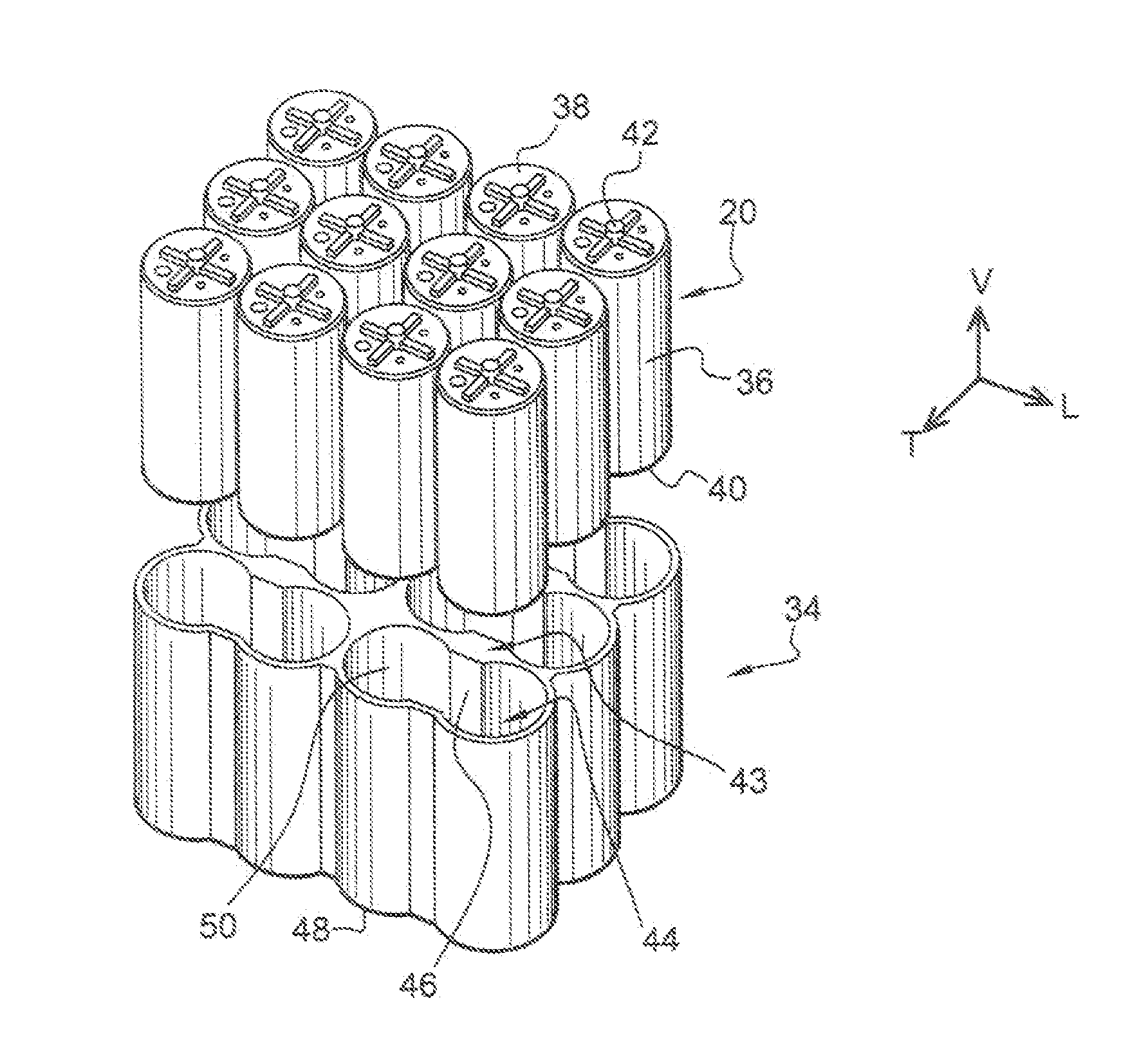
According to the invention which is represented in FIG. 9, the device comprises three pairs of adjacent storage units 20.

There is a single housing 32, and this therefore constitutes the tray for receipt of the units 20. A single hollow part is therefore provided for formation of receptacles 234 with an oblong form for the units 20. The units 20 are introduced transversely into the receptacles 234. These receptacles have a longitudinal orientation, with heat-conducting resin or heat-conducting glue 54 being interposed between the inner surfaces of the receptacles 234 and the outer surfaces of the units 20. According to one embodiment, the housing is made of aluminium. As a variant, the housing is made of copper.

The inner receptacles 234 with an oblong form are delimited by two portions with a semi-circular form and by two straight portions which connect the circumferential ends of the semi-circular portions to one another.

According to this embodiment, which is applicable to all the e...


PUM


Abstract

An electrical power supply device for a motor vehicle, which includes a tray made of a heat-conducting material, in which there is positioned at least one ultra-high capacity energy storage unit liable to emit heat, the tray including at least one housing to accommodate at least one electrical energy storage unit with the presence of a heat-conducting layer made of a heat conducting adhesive or a heat-conducting resin interposed without clearance between the storage unit and the interior face of the wall of the associated housing so as to conduct the heat emitted by the unit.

Description

FIELD OF THE INVENTIONThe invention relates to an electrical supply device for a motor vehicle, which comprises a tray in which there is provided at least one ultra high-capacity electrical energy storage unit which can emit heat, the said tray comprising at least one receptacle for receipt of at least one electrical energy storage unit.PRIOR ARTNumerous examples of devices of this type are known.Such electrical supply devices are used for example to supply electrical machines of motor vehicles of the electric and / or hybrid type, i.e. which combine an electrical machine and a conventional thermal engine, for which it is important to be able to recuperate the kinetic energy in order to re-charge the vehicle battery and to supply the on-board network with electric power. This function is commonly known as recuperative braking. A battery of the metal hydride type is used, for example.However, these electrical supply devices pose many problems.In fact, the energy storage units undergo m...

Claims


Application Information

Patent Timeline
Patent Type & Authority Applications(United States)
IPC IPC(8): H01G2/08H01G11/10H01G11/18H01G11/78
CPCH01G2/04H01G2/08H01G9/016H01G9/155Y02T10/7022H01G11/18H01G11/78Y02E60/13H01G11/10Y02T10/70H01G11/74H01M50/20H01M50/572
Inventor GUERIN, FABIENABADIA, ROGERRONDIER, PATRICK
Owner VALEO EQUIP ELECTRIC MOTEUR
Why Eureka
Try Eureka