Hearing aid

Inactive Publication Date: 2011-04-21
PANASONIC CORP
View PDF4 Cites 29 Cited by
  • Summary
  • Abstract
  • Description
  • Claims
  • Application Information

AI Technical Summary

Benefits of technology

[0011]Because the hearing aid of the present invention is constituted as above, the situation is evaluated by detecting movement of the user's face, and the audio signal inputted to the microp

Problems solved by technology

However, when the user and his family are sitting around a table while watching television, for exa

Method used


Image

  • Hearing aid
  • Hearing aid
  • Hearing aid

Examples


embodiment 1

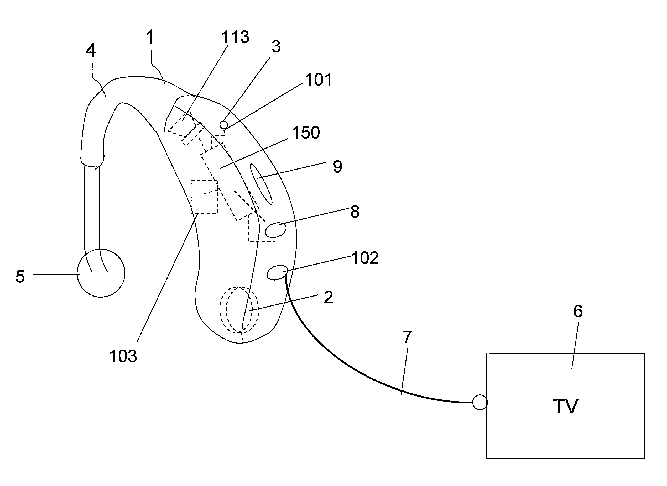
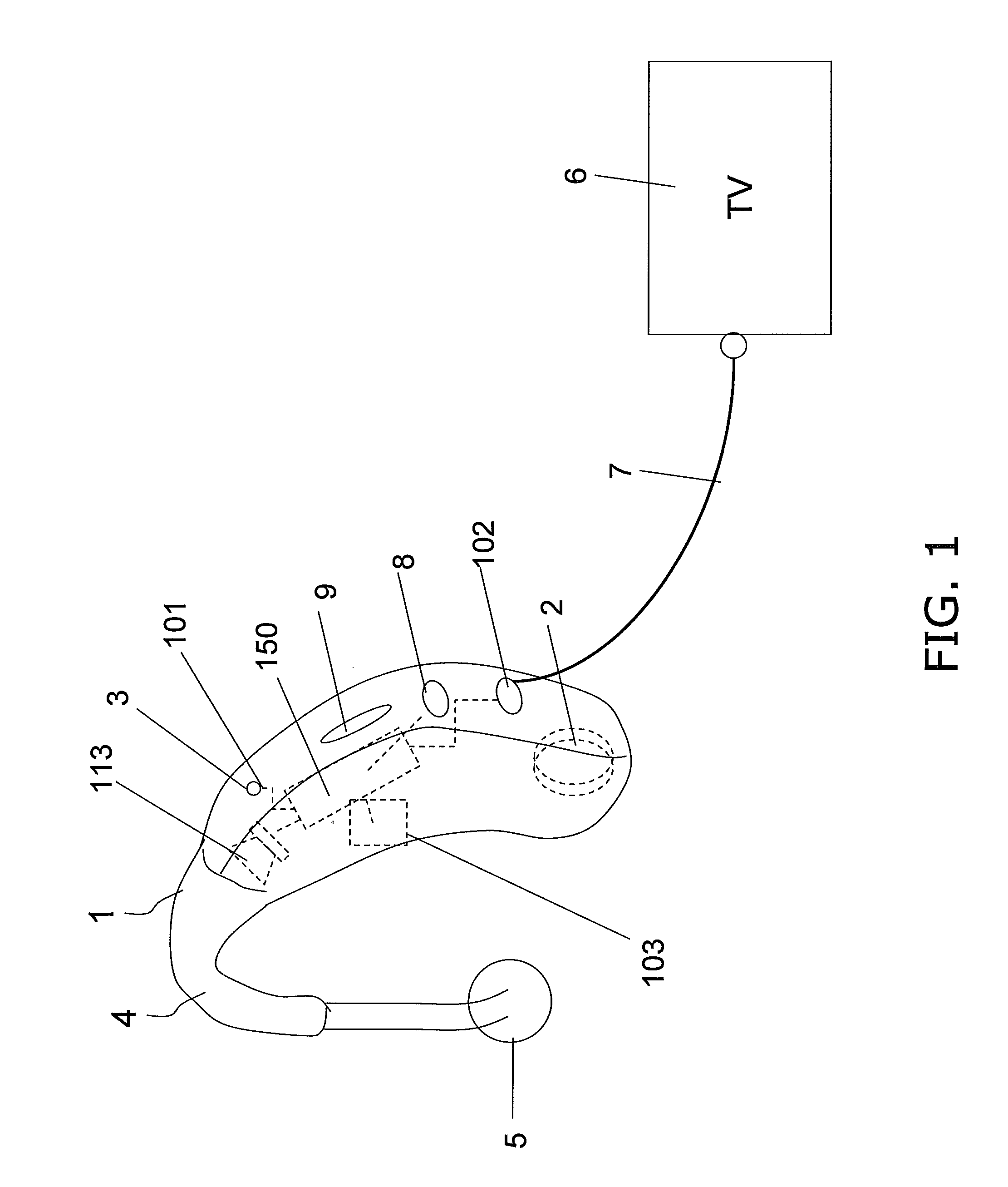
[0027]The hearing aid pertaining to Embodiment 1 of the present invention will be described through reference to FIGS. 1 to 9.

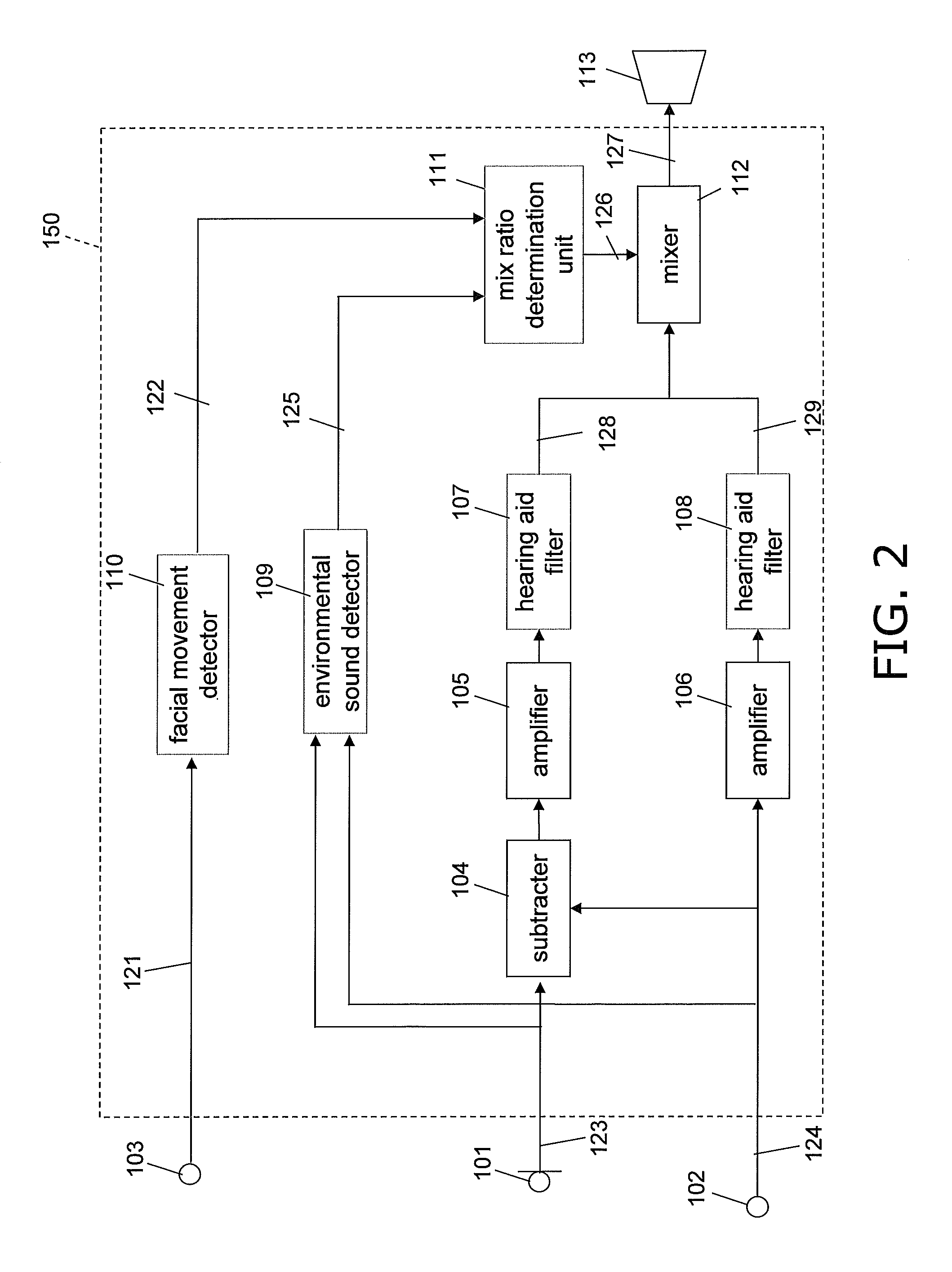
[0028]FIG. 1 is a diagram of the constitution of the hearing aid pertaining to Embodiment 1 of the present invention, and FIG. 2 is a block diagram of the hearing aid of FIG. 1. In FIGS. 1 and 2, 101 is a microphone, 102 is an external input terminal, 103 is an angular velocity sensor, 104 is a subtracter 104, 105 and 106 are amplifiers, 107 and 108 are hearing aid filters, 109 is an environmental sound detector, 110 is a facial movement detector, 111 is a mix ratio determination unit, 112 is a mixer 112, and 113 is a receiver.

[0029]The microphone 101, the external input terminal 102, the angular velocity sensor 103, the subtracter 104, the amplifiers 105 and 106, the hearing aid filters 107 and 108, the environmental sound detector 109, the facial movement detector 110, the mix ratio determination unit 111, the mixer 112, and the receiver 113 are all housed ...

embodiment 2

[0102]The hearing aid pertaining to another embodiment of the present invention will now be described through reference to FIG. 10.

[0103]FIG. 10 shows the configuration of the hearing aid pertaining to this embodiment.

[0104]As shown in FIG. 10, the hearing aid of this embodiment is a type of hearing aid that is inserted into the ear canal, and a main body case 10 has a cylindrical shape that is narrower on the distal end side and grows thicker toward the rear end side. That is, since the distal end side of the main body case 10 is inserted into the ear canal, that side is formed in a slender shape that allows it to be inserted into the ear canal.

[0105]With the hearing aid of this embodiment, the angular velocity sensor 103 is disposed on the rear end side of the main body case 10 disposed outside the ear canal.

[0106]Meanwhile, the receiver 113 is disposed on the distal end side of the main body case 10 inserted in the ear canal.

[0107]In other words, the angular velocity sensor 103 a...

embodiment 3

[0109]The hearing aid pertaining to yet another embodiment of the present invention will now be described through reference to FIG. 11.

[0110]FIG. 11 shows the configuration of the hearing aid pertaining to Embodiment 3.

[0111]As shown in FIG. 11, the hearing aid of this embodiment is a type that makes use of an ear hook 11, and a main body case 12 is connected further to the distal end side than the ear hook 11. The angular velocity sensor 103 is disposed inside this main body case 12.

[0112]In general, the ear hook 11 is made of a soft material to make it more comfortable to the ear. Accordingly, if the angular velocity sensor 103 is disposed inside the ear hook, there is the risk that movement of the user's face cannot be detected properly.

[0113]In view of this, with this embodiment the angular velocity sensor 103 is disposed within the main body case 12 connected on the distal end side of the ear hook 11. More specifically, the angular velocity sensor 103 is disposed near the mount...


PUM


Abstract

This hearing aid comprises a microphone (101) and an external input terminal (102), a hearing aid processor (150) to which audio signals from the microphone (101) and the external input terminal (102) are inputted, and a receiver (113) to which audio signals that have undergone hearing aid processing by this hearing aid processor (150) are outputted. The hearing aid processor (150) has a mixer (112) that mixes audio signals from the microphone (101) with audio signals from the external input terminal (102) and outputs these audio signals to the receiver (113), a mix ratio determination unit (111) for determining the mix ratio between audio signals from the microphone (101) and audio signals from the external input terminal (102) in this mixer (112), and a facial movement detector (110) that is connected to this mix ratio determination unit (111).

Description

TECHNICAL FIELD[0001]The present invention relates to a hearing aid with which audio signals inputted from a television or other such external device to an external input terminal (external input signals) are outputted to a receiver in addition to audio signals acquired by a microphone (microphone input signals).BACKGROUND ART[0002]Recent years have witnessed proposals for a hearing aid that receives the audio of a television, CD, or other such external device directly from an external input terminal via wireless means (such as by Bluetooth), rather than picking up the sound with a microphone.[0003]With this hearing aid, the audio of a television, CD, or other such external device can be enjoyed as a clear sound that is free from noise. This makes the hearing aid more pleasant to use for the user.[0004]However, when the user and his family are sitting around a table while watching television, for example, the user may be unable to catch his family's conversation that is received by ...

Claims


Application Information

Patent Timeline
IPC IPC(8): H04R25/00
CPCH04R25/43H04R25/48H04S7/304H04R25/556H04R2225/41H04R25/554H04R25/607
Inventor NISHIZAKI, MAKOTONAKATOH, YOSHIHISA
Owner PANASONIC CORP
Why Eureka
Try Eureka