Surgical system

a surgical system and suction pump technology, applied in the field of surgical systems, can solve problems such as contamination of irrigation lines, and achieve the effect of rapid pressure compensation

Inactive Publication Date: 2011-04-21
CARL ZEISS MEDITEC AG
View PDF11 Cites 14 Cited by
  • Summary
  • Abstract
  • Description
  • Claims
  • Application Information

AI Technical Summary

Benefits of technology

[0008]It is therefore an object of the invention to provide a surgical system which permits rapid pressure compensation when there is an underpressure in an aspiration line, wherein a sharp drop in pressure in the irrigation line is avoided at atmospheric pressure. It is also an object of the invention to provide a method for operating a surgical system of this kind.
[0010]In the event of an occlusion in the aspiration line, the system according to the invention allows fluid from the second fluid vessel to be routed through the aspiration venting line into the aspiration inlet line. By means of the second pressure in the second fluid vessel, the fluid is conveyed at high speed and with a substantial pulse to the needle tip, counter to the normal fluid transport direction, and is able to force the particle blocking the needle tip out of the needle tip. The second pressure must be selected so high as to allow the particle to be forced out of the needle tip; if appropriate, the second pressure provided by the pneumatic pressure system must be increased. The particular advantage of using the pneumatic pressure system is that very rapid venting in the millisecond range is possible, while at the same time, the pressure in the irrigation line and thus also the intraocular pressure fluctuates only very slightly, if at all.
[0011]The fluid delivered does not originate from the first fluid vessel, which contains the irrigation fluid and is connected to the irrigation line. A complete separation from this first fluid vessel is achieved by the second fluid vessel, such that no direct pressure fluctuations can occur in the irrigation line during the venting procedure. Moreover, the separation of the two fluid vessels rules out the possibility of contamination of the irrigation line. Since the second fluid vessel contains sterile fluid, contamination of the aspiration line by the venting procedure is also ruled out. It is thus possible to use the surgical system on several patients treated in succession, without danger of contamination with impurities that have previously been introduced.
[0012]According to a preferred embodiment, the second fluid vessel can be filled through a filling line that has a filling valve, wherein the filling line is connected at one end to the irrigation line. It thus suffices to fill only the first fluid vessel with irrigation fluid, such that the second fluid vessel can subsequently be filled from this sterile fluid. Such filling of the second fluid vessel can take place, for example, before the start of a surgical procedure. The filling valve provides a reliable separation between the irrigation line and that part of the filling line directed toward the second fluid vessel. The filling valve also reliably separates the different fluid pressures that exist in the irrigation line and in the second fluid vessel.
[0016]If the irrigation line has an irrigation valve, the latter can be brought to such a position that the irrigation line is interrupted. If the irrigation valve in the irrigation line is arranged between handpiece and filling line, the second fluid vessel can be filled particularly quickly with fluid from the first fluid vessel by way of the filling line. In this case, during the filling of the second fluid vessel, no pressure fluctuations occur in that part of the irrigation line arranged between irrigation valve and handpiece. This therefore ensures that no pressure fluctuations are induced in the eye during the filling of the second fluid vessel.

Problems solved by technology

Moreover, the separation of the two fluid vessels rules out the possibility of contamination of the irrigation line.

Method used


Image

  • Surgical system
  • Surgical system
  • Surgical system

Examples


Embodiment Construction

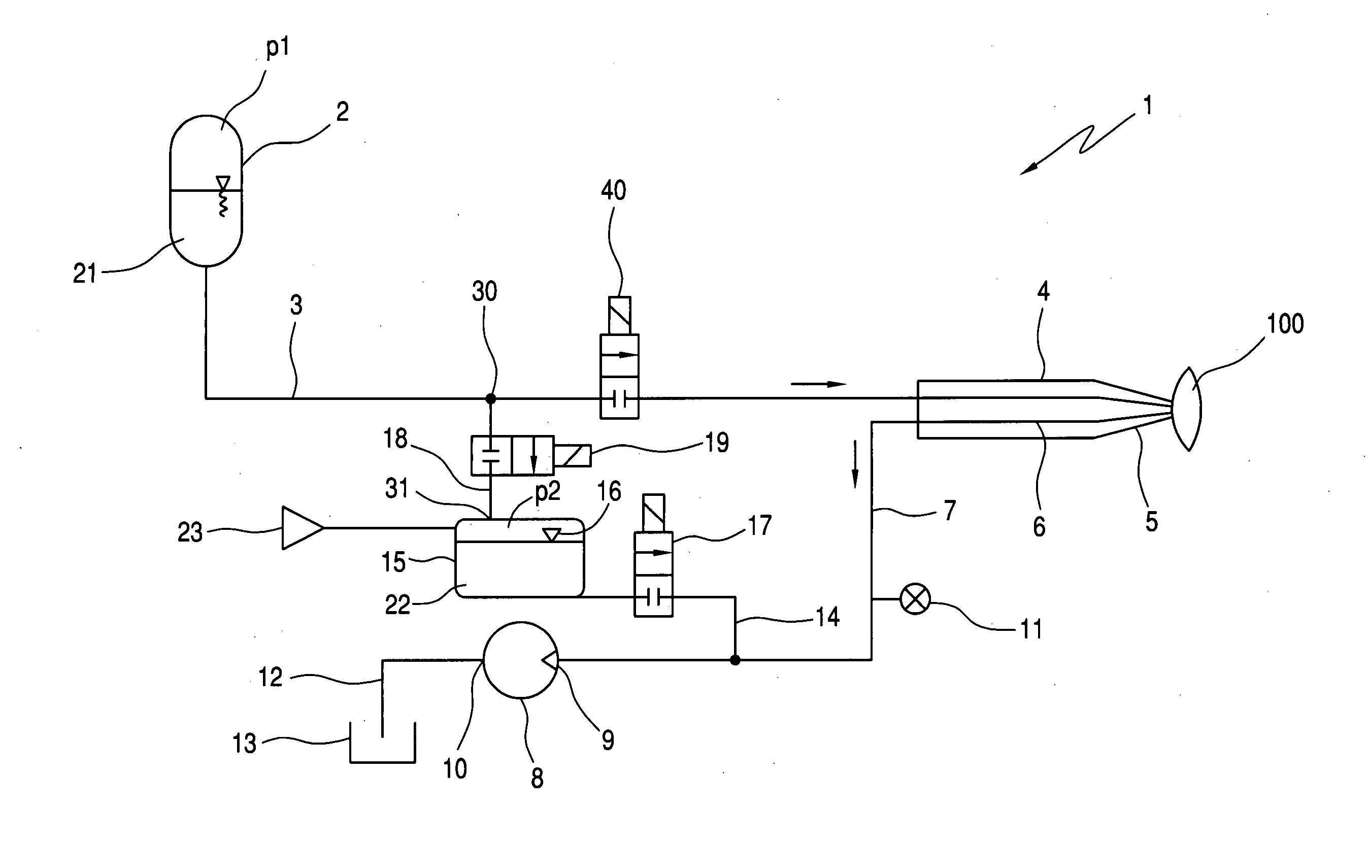
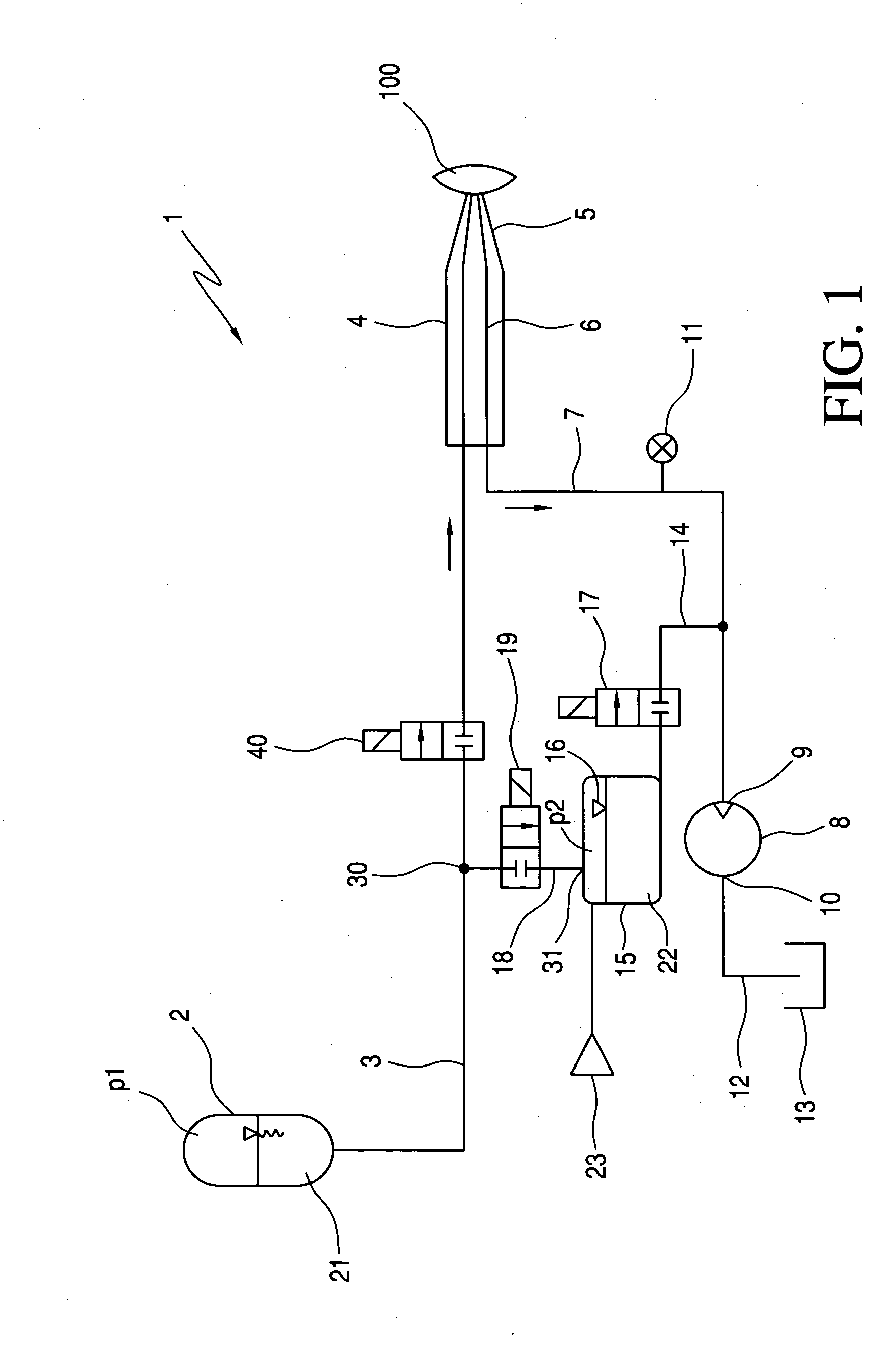
[0022]FIG. 1 is a schematic representation of an embodiment of the surgical system 1 according to the invention. A first fluid vessel 2 contains an irrigation fluid 21 that can be conveyed through an irrigation line 3 to a surgical handpiece 4. The handpiece 4 can be a phaco-emulsification handpiece in which a vibrating tip 5 emulsifies a clouded lens of an eye and the broken lens fragments are aspirated off. An irrigation valve 40, which is shown as a two-way valve in FIG. 1, enables or blocks a flow of the irrigation fluid in the direction of the handpiece 4. From the tip 5, an aspiration line 6 runs to one end of the handpiece 4 in order to transport emulsified lens fragments and fluid away from the eye. They are transported away by a suction pump 8 which, at its inlet 9, is connected to the handpiece 4 via an aspiration inlet line 7. A fluid pressure in the aspiration inlet line 7 is detected by a pressure sensor 11 which is arranged between the inlet 9 of the suction pump 8 and...


PUM


Abstract

A surgical system (1) for controlling a fluid includes an irrigation line (3), which is connected at one end to a first fluid vessel (2) for holding irrigation fluid (21) and is connected at another end to a surgical handpiece (4). The irrigation fluid (21) can be delivered at a first pressure (p1) to the handpiece (4). The surgical system further includes an aspiration inlet line (7), a second fluid vessel (15) for holding irrigation fluid (22), an aspiration venting line (14), which connects the second fluid vessel (15) to the aspiration inlet line (7), a venting valve (17), which is provided in the aspiration venting line (14) and which can switch in dependence on the fluid pressure in the aspiration inlet line (7) and / or irrigation line (3). The second fluid vessel (15) is connected to a pneumatic pressure system (23) with which the fluid (22) in the second fluid vessel (15) can be subjected to a second pressure (p2) that is higher than the first pressure (p1) in the first fluid vessel (2).

Description

CROSS REFERENCE TO RELATED APPLICATIONS[0001]This application is a continuation application of international patent application PCT / EP 2009 / 003715, filed May 26, 2009, designating the United States and claiming priority from German application 10 2008 026 014.2, filed May 30, 2008, and the entire content of both applications is incorporated herein by reference.FIELD OF THE INVENTION[0002]The invention relates to a surgical system and a method for controlling fluid during the treatment of cataract by phacoemulsification.BACKGROUND OF THE INVENTION[0003]There are several surgical techniques for treatment of clouding of the lens, which is referred to in medicine as gray cataract. The most widely used technique is phacoemulsification, in which a thin tip is introduced into the diseased lens and is excited to vibration with ultrasound. In its immediate environment, the vibrating tip emulsifies the lens in such a way that the resulting lens fragments can be sucked through a line by a pump...

Claims


Application Information

Patent Timeline
Patent Type & Authority Applications(United States)
IPC IPC(8): A61M1/00A61F9/007
CPCA61F9/00745A61M2210/0612A61M1/0058A61M1/0031A61M1/74A61M1/77
Inventor KUEBLER, CHRISTOPHKRAUS, MARTINEICHLER, MICHAELMAIER, TOBIAS
Owner CARL ZEISS MEDITEC AG
Why Eureka
Try Eureka