Nasal Dilator and Methods of Fabricating Medical Devices

a technology of nasal dilators and medical devices, applied in the field of nasal dilators and methods of fabricating medical devices, can solve the problems of nasal passage malformation, sleep disturbance, irregularities and general discomfort, and achieve the effects of reducing manufacturing costs, easy removal, and little or no stress

Active Publication Date: 2011-04-21
HORIZON IP TECH LLC
View PDF2 Cites 40 Cited by
  • Summary
  • Abstract
  • Description
  • Claims
  • Application Information

AI Technical Summary

Benefits of technology

[0027]The single body truss comprises horizontal regions, including first and second end regions adapted to engage outer wall tissues of first and second nasal-passages, respectively, and an intermediate region adapted to traverse a portion of a nose located between the first and second nasal passages and joining the end regions. The truss is capable of resilient deformation such that when flexed it returns substantially to its pre-flexed state. In use the dilator stabilizes nasal outer wall tissues, and may further expand or dilate the nasal outer walls to prevent tissues thereof from drawing inward during breathing. The truss is configured to be comfortable on the skin surfaces engaged and to be easily removed with little or no stress thereto.
[0028]It

Problems solved by technology

A portion of the human population has some malformation of the nasal passages which interferes with breathing, including deviated septa, swelling due to infection or allergic reactions, or inflammation due to changes in atmospheric humidity.
Blockage of the nasal passages as a result of malformation, symptoms of the common cold or seasonal allergies are particularly uncomfortable at night, and can lead to sleep disturbances, irregularities and general discomfort.
Constructing a nasal dilator with less than 15 grams of spring biasing force may not provide suitable stabilization or dilation, while greater than 35 grams would be uncomfortable for most users.
Using a more aggressive adhesive, a greater amount of adhesive, or greater adhesive surface area so as to withstand greater spring biasing increases the likelihood of damage to the tissue upon removal of the device.
A particular inherent limitation of the external nasal dilator is that spring biasing creates peel forces at its opposite end regions, together with some tensile forces, which act to disengage the device from the skin surface.
Howeve

Method used


Image

  • Nasal Dilator and Methods of Fabricating Medical Devices
  • Nasal Dilator and Methods of Fabricating Medical Devices
  • Nasal Dilator and Methods of Fabricating Medical Devices

Examples


Embodiment Construction

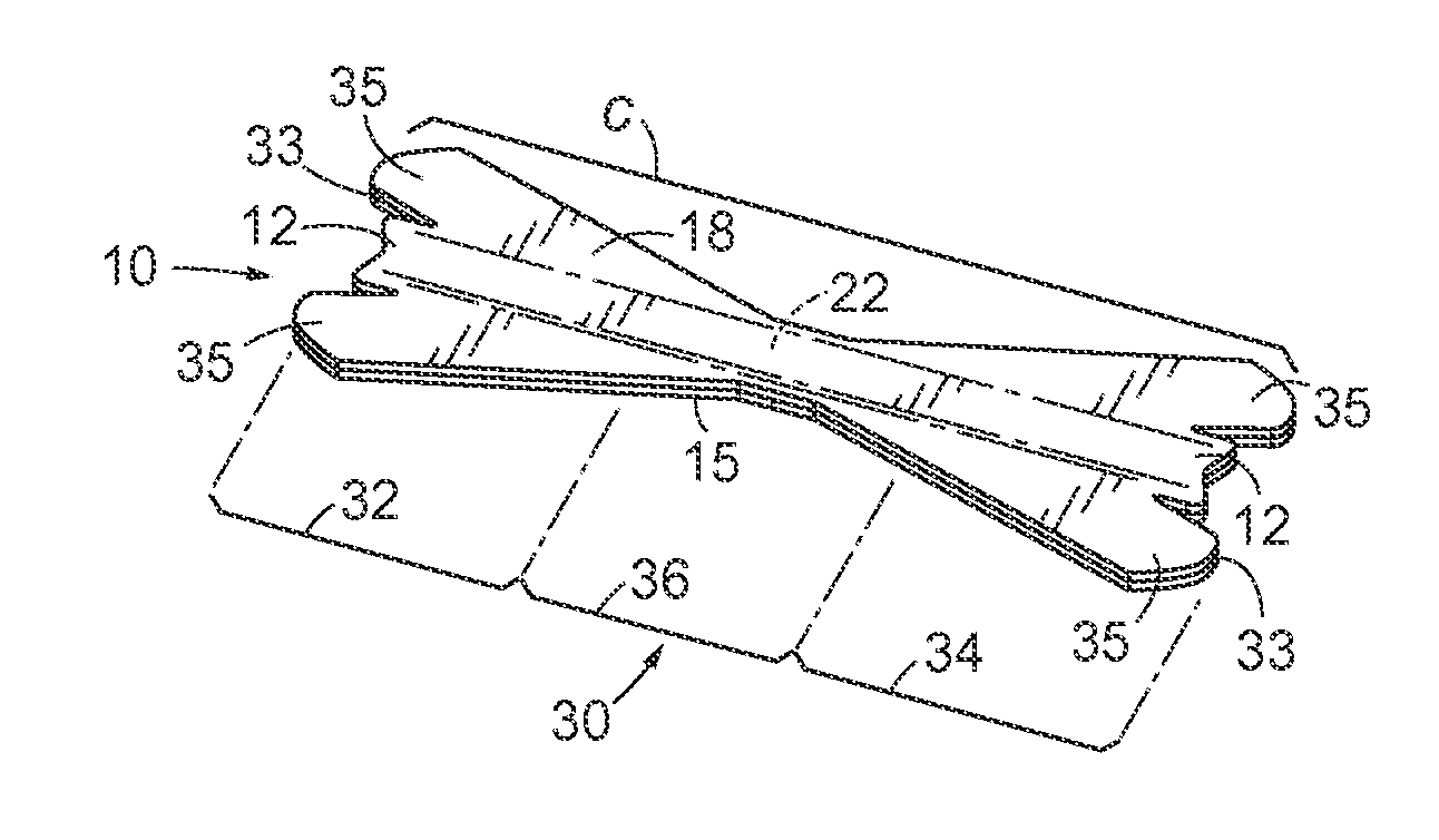
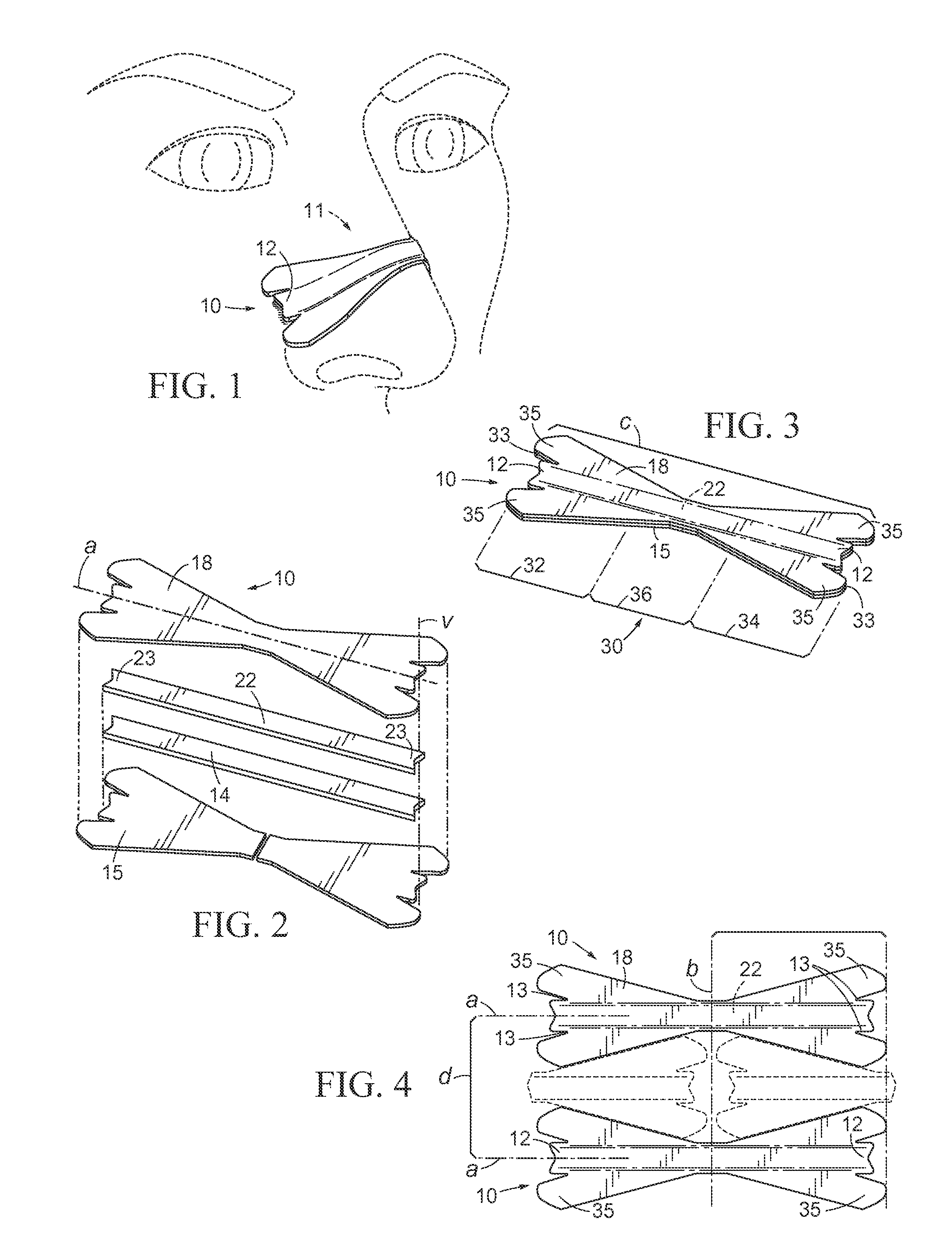
[0103]An embodiment of a nasal dilator, 10, in accordance with the present invention is illustrated in FIG. 1. Seen in use, dilator 10 is affixed by its engagement element to a nose, 11, illustrated as a portion of a human face. Dilator 10 includes a directional element in the form of a horizontal protrusion, 12, which separates slightly from the skin thereat as a result of the device's functional element applying spring biasing forces to the nasal wall tissues when dilator 10 is flexed across the bridge of the nose.

[0104]FIG. 2 shows that dilator 10 comprises a laminate of vertically stacked layers, indicated by a broken line, v, the layers including: a base layer comprising at least one base member, 14, a resilient layer comprising at least one resilient member, 22, and a cover layer comprising at least one cover member, 18. A base, resilient or cover member may further include one or more components as part thereof. Portions of one layer may overlap another layer. A protective la...


PUM

PropertyMeasurementUnit
Thicknessaaaaaaaaaa
Shapeaaaaaaaaaa
Widthaaaaaaaaaa

Abstract

Methods are disclosed for converting on a mass scale elongated material webs into finished parts or devices. Slits form strands in a web, the strands comprising interconnected objects which correspond to parts of finished devices. Strands are combined with additional webs to form a material laminate from which finished devices are die cut. The methods are suitable for a range of converting applications including medical devices, particularly the external nasal dilator. Complex dilator devices produced from the methods are formed as a single body truss having horizontal regions adapted to engage outer wall tissues of first and second nasal passages of a nose. When in use the dilator stabilizes or expands nasal outer wall tissues and prevents the outer wall tissues from drawing inward during breathing. Methods of manufacture comprise separate steps for fabricating and assembling the elements and layers of finished dilator devices and for packaging finished devices individually or in groups. Waste material is incorporated into subsequent fabrication processes to produce the same or complementary devices.

Description

RELATED APPLICATIONS[0001]This application is a Continuation in Part of Non Provisional patent application Ser. Nos. 12 / 402,214 filed 11 Mar. 2009, 12 / 106,289 filed 19 Apr. 2008, and 12 / 024,763 filed 1 Feb. 2008. Application Ser. No. 12 / 402,214 claims priority benefit of Provisional Patent Application No. 61 / 035,972 filed 12 Mar. 2008. Application Ser. No. 12 / 106,289 claims priority benefit of Provisional Patent Application No. 60 / 913,271 filed 21 Apr. 2007. Application Ser. No. 12 / 024,763 claims priority benefit of Provisional Patent Application No. 60 / 888,543 filed 6 Feb. 2007.FIELD OF THE INVENTION[0002]The present invention relates generally to converting elongated material webs into finished parts or devices such as may be used in the medical, high-technology, electronics, automotive or aerospace industries. The methods are particularly suited to the converting of elongated sheets or rolls of thin flexible materials such as papers, films, foils, tapes, synthetic fabrics and the...

Claims


Application Information

Patent Timeline
IPC IPC(8): A61F5/08B32B38/10
CPCY10T156/1069A61F5/08Y10T156/1087Y10T156/1074A61M2210/0618Y10T156/1085Y10T156/1075
Inventor IERULLI, JOSEPH V.
Owner HORIZON IP TECH LLC
Why Eureka
Try Eureka