
Micro-Fluid Ejection Devices, Methods for Making Micro-Fluid Ejection Heads, And Micro-Fluid Ejection Head Having High Resistance Thin Film Heaters

The use of thin film heaters composed of silicon, metal, and carbon in micro-fluid ejection heads addresses the need for higher resistance and reduced energy consumption, achieving efficient and consistent fluid ejection with lower parasitic sensitivity and cost-effective substrate design.

Active Publication Date: 2011-04-28
FUNAI ELECTRIC CO LTD
View PDF8 Cites 7 Cited by
  • Summary
  • Abstract
  • Description
  • Claims
  • Application Information

AI Technical Summary

Benefits of technology

The solution provides micro-fluid ejection heads with lower energy requirements, reduced sensitivity to parasitic resistance, and the ability to use smaller drive transistors, resulting in a smaller substrate area and lower costs, while maintaining high resistance and uniformity, enabling efficient and consistent fluid ejection.

Problems solved by technology

As the capabilities of micro-fluid ejection devices are increased to provide higher ejection rates, the ejection heads, which are the primary components of micro-fluid devices, continue to evolve and become more complex.

Method used


Image

  • Micro-Fluid Ejection Devices, Methods for Making Micro-Fluid Ejection Heads, And Micro-Fluid Ejection Head Having High Resistance Thin Film Heaters
  • Micro-Fluid Ejection Devices, Methods for Making Micro-Fluid Ejection Heads, And Micro-Fluid Ejection Head Having High Resistance Thin Film Heaters
  • Micro-Fluid Ejection Devices, Methods for Making Micro-Fluid Ejection Heads, And Micro-Fluid Ejection Head Having High Resistance Thin Film Heaters

Examples


Embodiment Construction

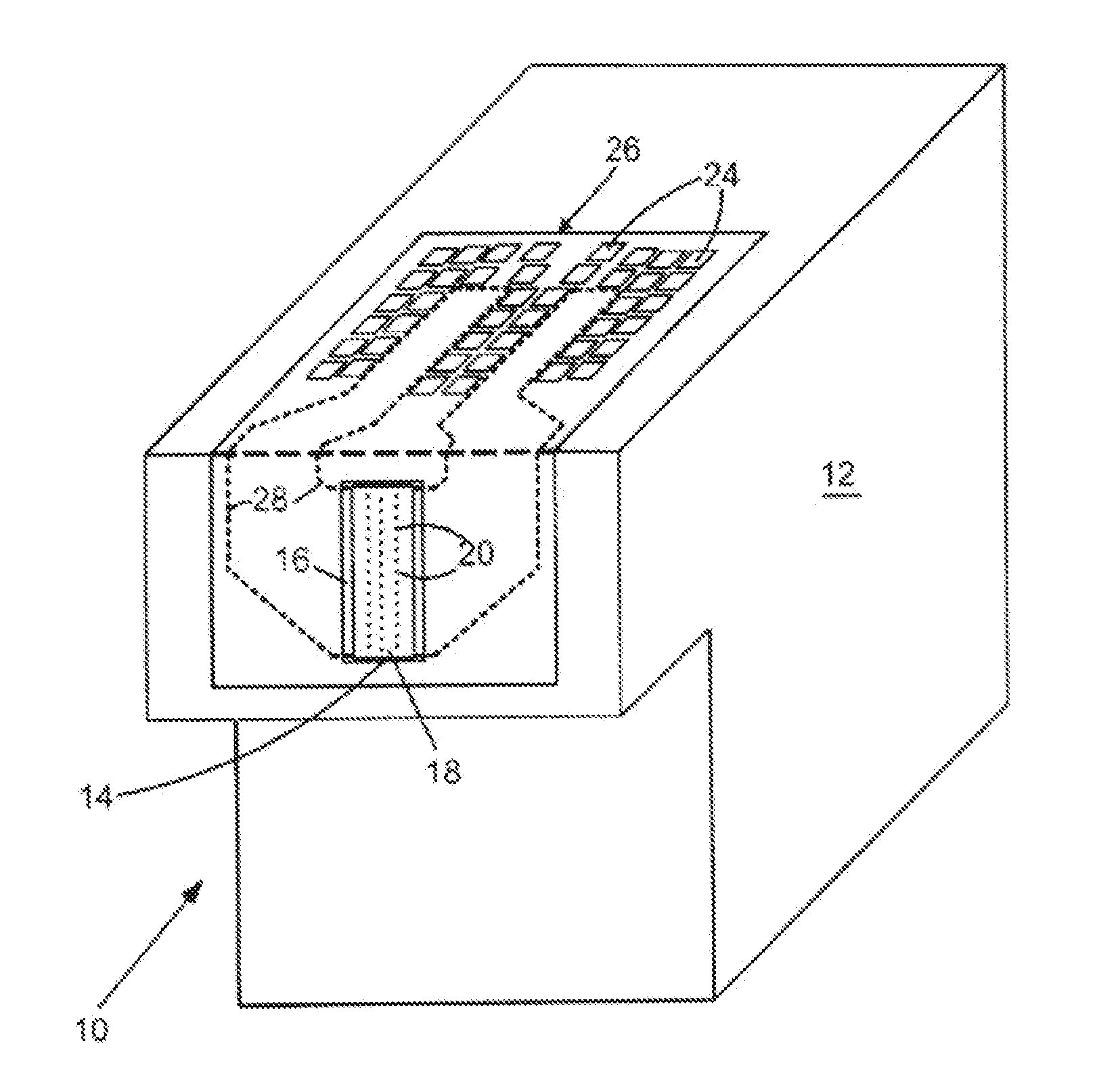
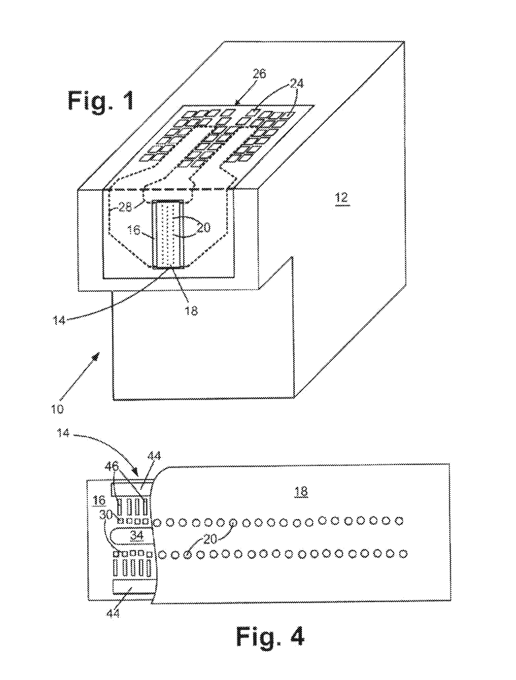
[0016]With reference to FIG. 1, a fluid cartridge 10 for a micro-fluid ejection device is illustrated. The cartridge 10 includes a cartridge body 12 for supplying a fluid to a micro-fluid ejection head 14. The fluid may be contained in a storage area in the cartridge body 12 or may be supplied from a remote source to the cartridge body.

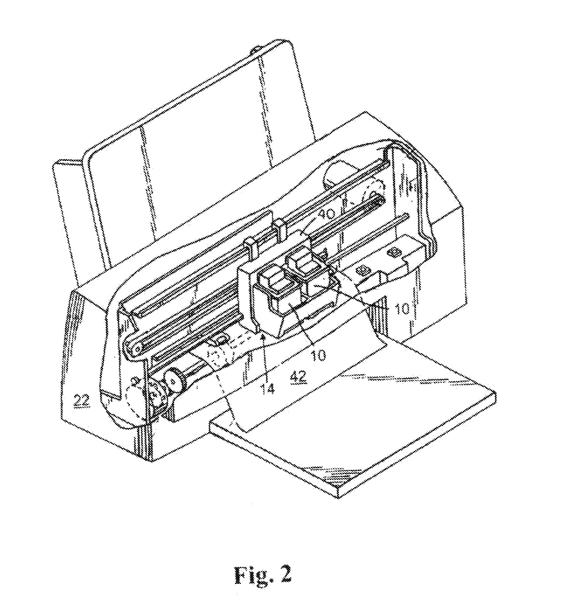
[0017]The exemplary micro-fluid ejection head 14 includes a substrate 16 and a nozzle plate 18 containing nozzles 20. The cartridge 10 may be removably attached to a micro-fluid ejection device such as an ink jet printer 22 (FIG. 2). Accordingly, electrical contacts 24 are provided on a flexible circuit 26 for electrically connecting the cartridge 10 to the micro-fluid ejection device 22. The flexible circuit 26 includes electrical traces 28 that are connected to the substrate 16 of the micro-fluid ejection head 14.

[0018]An enlarged cross-section view, not to scale, of a portion of the micro-fluid ejection head 14 is illustrated in FIG. 3. The micro-f...


PUM

PropertyMeasurementUnit
ohms per squareaaaaaaaaaa
dimensionaaaaaaaaaa
length dimension Daaaaaaaaaa

Abstract

Micro-fluid ejection devices, methods for making micro-fluid ejection heads, and micro-fluid ejection heads, including a micro-fluid ejection head. One such micro-fluid ejection head has relatively high resistance thin film heaters adjacent to a substrate. The thin film material comprises silicon, metal, and carbon (SiMC wherein M is a metal). Each thin film heater has a sheet resistance ranging from about 100 to about 600 ohms per square and a thickness ranging from about 100 to about 800 Angstroms.

Description

[0001]This is a divisional application of U.S. patent application Ser. No. 11 / 683,572 filed Mar. 8, 2007, now U.S. Pat. No. 7,673,972, entitled “MICRO-FLUID EJECTION DEVICES, METHODS FOR MAKING MICRO-FLUID EJECTION HEADS, AND MICRO-FLUID EJECTION HEADS HAVING HIGH RESISTANCE THIN FILM HEATERS.”TECHNICAL FIELD[0002]The disclosure relates to micro-fluid ejection heads and, in a particular exemplary embodiment, to thin film heater resistors having high resistance.BACKGROUND AND SUMMARY[0003]Micro-fluid ejection devices such as ink jet printers continue to experience wide acceptance as economical replacements for laser printers. Micro-fluid ejection devices also are finding wide application in other fields such as in the medical, chemical, and mechanical fields. As the capabilities of micro-fluid ejection devices are increased to provide higher ejection rates, the ejection heads, which are the primary components of micro-fluid devices, continue to evolve and become more complex.[0004]Fo...

Claims


Application Information

Patent Timeline
Patent Type & Authority Applications(United States)
IPC IPC(8): B23P17/00
CPCB41J2/14129Y10T29/49401B41J2202/11B41J2202/03
Inventor GUAN, YIMINJACOBSEN, STUARTSULLIVAN, CARL
Owner FUNAI ELECTRIC CO LTD
Learn More