Fuel injection valve
a fuel injection valve and valve body technology, applied in the direction of fuel injection apparatus, spraying apparatus, feeding system, etc., can solve the problems of inability to control the injection quantity with high accuracy, the adverse effect of the restricting effect in the communicating hole, and the large pressure pulsation of the fuel discharged from the control chamber, etc., to achieve the effect of shortening suppressing the adverse effect caused by the length of the narrow part, and shortening the narrow par
- Summary
- Abstract
- Description
- Claims
- Application Information
AI Technical Summary
Benefits of technology
Problems solved by technology
Method used
Image

Examples
first embodiment
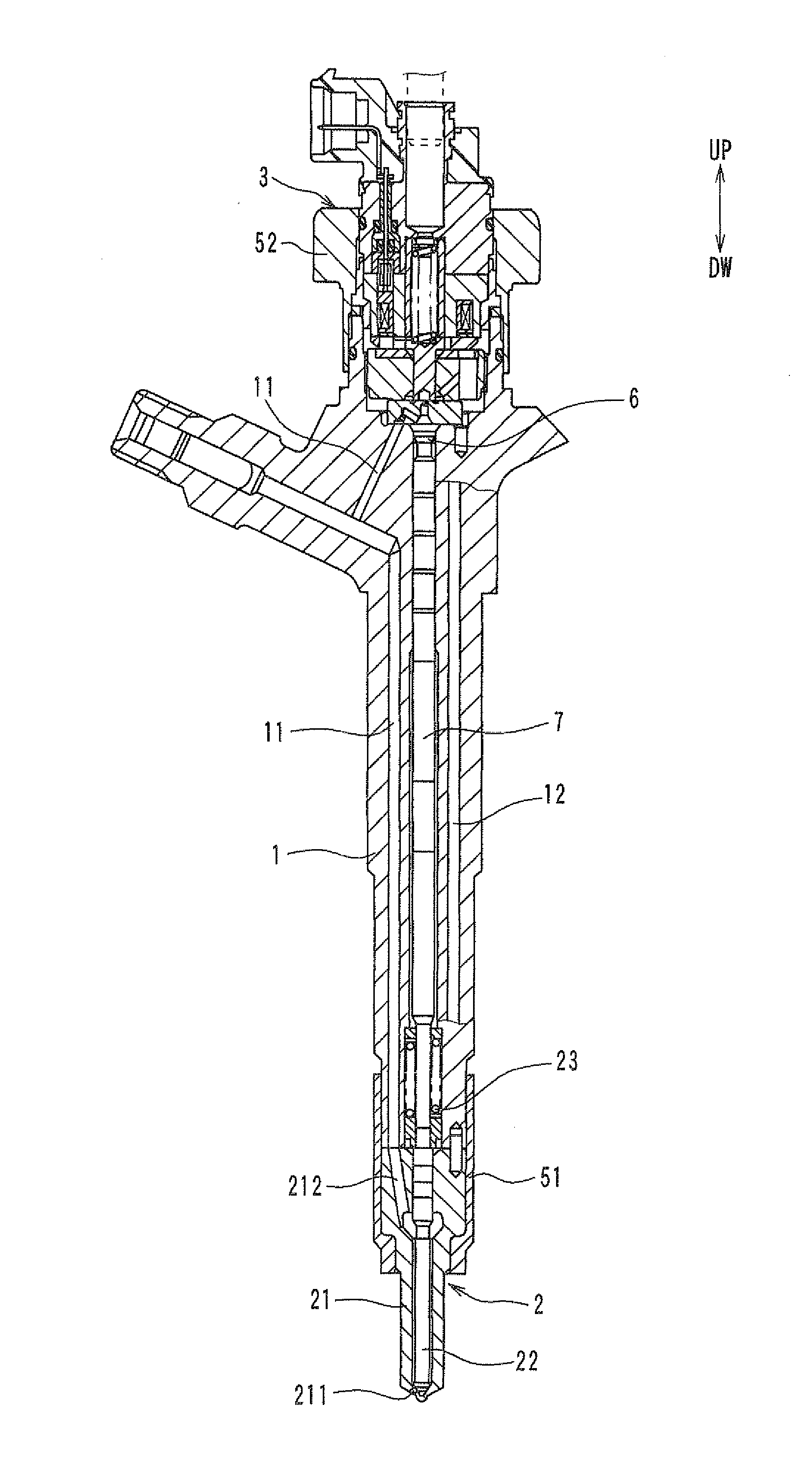
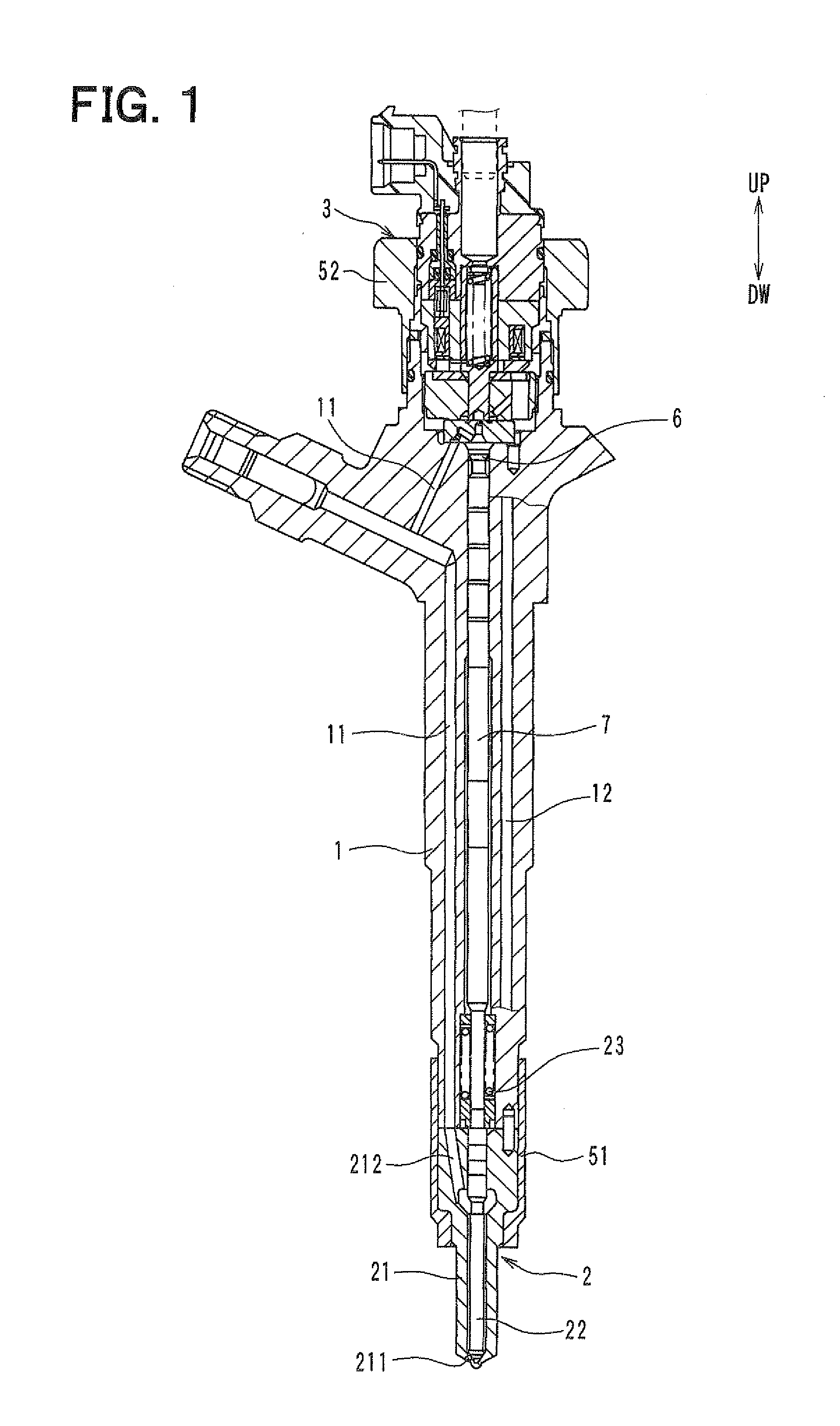
[0026]FIG. 1 is a sectional view showing a fuel injection valve according to a first embodiment of the present invention. FIG. 2 shows an enlarged view of the fuel injection valve corresponding to an upper part in FIG. 1. In the drawings, an arrow symbol with UP and DW indicates a vertical direction of the fuel injection valve when it is mounted on the engine.
[0027]The fuel injection valve is mounted on a cylinder head of an internal combustion engine, e.g., a diesel engine. The fuel injection valve is connected to a common rail for being supplied pressurized fuel and an electronic control unit. The fuel injection valve injects fuel supplied from the common rail into a cylinder of the engine.
[0028]As shown in FIG. 1, the fuel injection valve is formed in a stick shape which can be characterized by a first end on a lower side and a second end on an upper side. A holder body 1 provides a main part of the fuel injection valve. The holder body 1 is formed in a cylindrical shape having a...
second embodiment
[0060]A second embodiment is described by referring to FIG. 4 which shows an enlarged sectional view of a fuel injection valve.
[0061]Only a part of the housing 40 in this embodiment is different from the preceding embodiment. The remaining components are the same or similar to those in the preceding embodiment. Therefore, differences are mainly explained below.
[0062]As shown in FIG. 4, the housing 40 of this embodiment has no extended hole 404. Alternatively, an extended hole 407 is formed in the housing 40 instead of the extended hole 404. The extended hole 407 provides a fluid communication between the lower hole 401 and the housing-communicating hole 403. The housing-communicating hole 403 provides a narrow passage of a narrow part in the discharge passage. The extended hole 407 provides a part of the discharge passage. The extended hole 407 has a diameter larger than that of the housing-communicating hole 403. The diameter of the extended hole 407 is equal to the diameter of the...
third embodiment
[0066]A third embodiment is described by referring to FIG. 5 which shows an enlarged sectional view of a fuel injection valve.
[0067]Only a part of the stopper 39 and the housing 40 in this embodiment is different from the preceding embodiments. The remaining components are the same or similar to those in the preceding embodiments. Therefore, differences are mainly explained below.
[0068]As shown in FIG. 5, the stopper 39 of this embodiment is formed in a cylindrical shape which has a cylindrical wall 392 and a bottom wall 393. The stopper 39 is inserted in the stator hole 331 and the lower hole 401. The bottom wall 393 is placed to come in contact with a bottom 406 of the lower hole 401. The spring 37 and the shim plate 38 are inserted in the solenoid passage 391. The spring 37 is disposed to come in contact with the bottom wall 393 of the stopper 39.
[0069]The stopper 39 defines a solenoid passage 391 there inside. The spring 37 is arranged in the solenoid passage 391. The solenoid p...
PUM
 Abstract
Description
Claims
Application Information
 - R&D
- Intellectual Property
- Life Sciences
- Materials
- Tech Scout
- Unparalleled Data Quality
- Higher Quality Content
- 60% Fewer Hallucinations
Browse by: Latest US Patents, China's latest patents, Technical Efficacy Thesaurus, Application Domain, Technology Topic, Popular Technical Reports.
© 2025 PatSnap. All rights reserved.Legal|Privacy policy|Modern Slavery Act Transparency Statement|Sitemap|About US| Contact US: help@patsnap.com