Enhancement of Power Management Using Dynamic Voltage and Frequency Scaling and Digital Phase Lock Loop High Speed Bypass Mode

a technology of dynamic voltage and frequency scaling and bypass mode, applied in the direction of electrical equipment, pulse automatic control, etc., can solve the problems of corrupted memory access, heavy and undesirable software management, and on-going access to devices such as memory may be corrupted, so as to improve the operation of locked loop

Active Publication Date: 2011-04-28
TEXAS INSTR INC
View PDF4 Cites 20 Cited by
  • Summary
  • Abstract
  • Description
  • Claims
  • Application Information

AI Technical Summary

Problems solved by technology

For example, voltage and frequency changes impact delay-locked loops (DLLs) used in interfaces such as memory controllers by causing loss of lock of the delay-locked loops (DLLs) so that on-going accesses to devices such as memory may be corrupted.
For conventional devices to continue to process properly during frequency transitions requires heavy and undesirable software management, for example.
Performing dynamical voltage and frequency scaling (DVFS) conventionally on an interface such as a memory controller causes the delay-locked loop (DLL) or any equivalent delay control cell, used, for example, to manage an external double data rate (DDR) memory, to lose its lock and, therefore, corrupt memory accesses.
However, each of the digital phase-locked loops (DPLLs) in each of the asynchronous clock domains generates a high speed synthesized clock and has a significant dynamic power consumption.
Furthermore, when a new synthesized frequency value is programmed on a given digital phase-locked loop (DPLL), for example, in a dynamic voltage and frequency scaling (DVFS) context, processing performance is negatively impacted during the digital phase-locked loop (DPLL) re-lock operation.

Method used


Image

  • Enhancement of Power Management Using Dynamic Voltage and Frequency Scaling and Digital Phase Lock Loop High Speed Bypass Mode
  • Enhancement of Power Management Using Dynamic Voltage and Frequency Scaling and Digital Phase Lock Loop High Speed Bypass Mode
  • Enhancement of Power Management Using Dynamic Voltage and Frequency Scaling and Digital Phase Lock Loop High Speed Bypass Mode

Examples


Embodiment Construction

[0015]Illustrative embodiments of the present claimed subject matter are described in detail below. In the interest of clarity, not all features of an actual implementation are described in this specification. It will of course be appreciated that in the development of any such actual embodiment, numerous implementation-specific decisions must be made to achieve the developers' specific goals, such as compliance with system-related and business-related constraints, which will vary from one implementation to another. Moreover, it will be appreciated that such a development effort would be a routine undertaking for those of ordinary skill in the art having the benefit of the present disclosure.

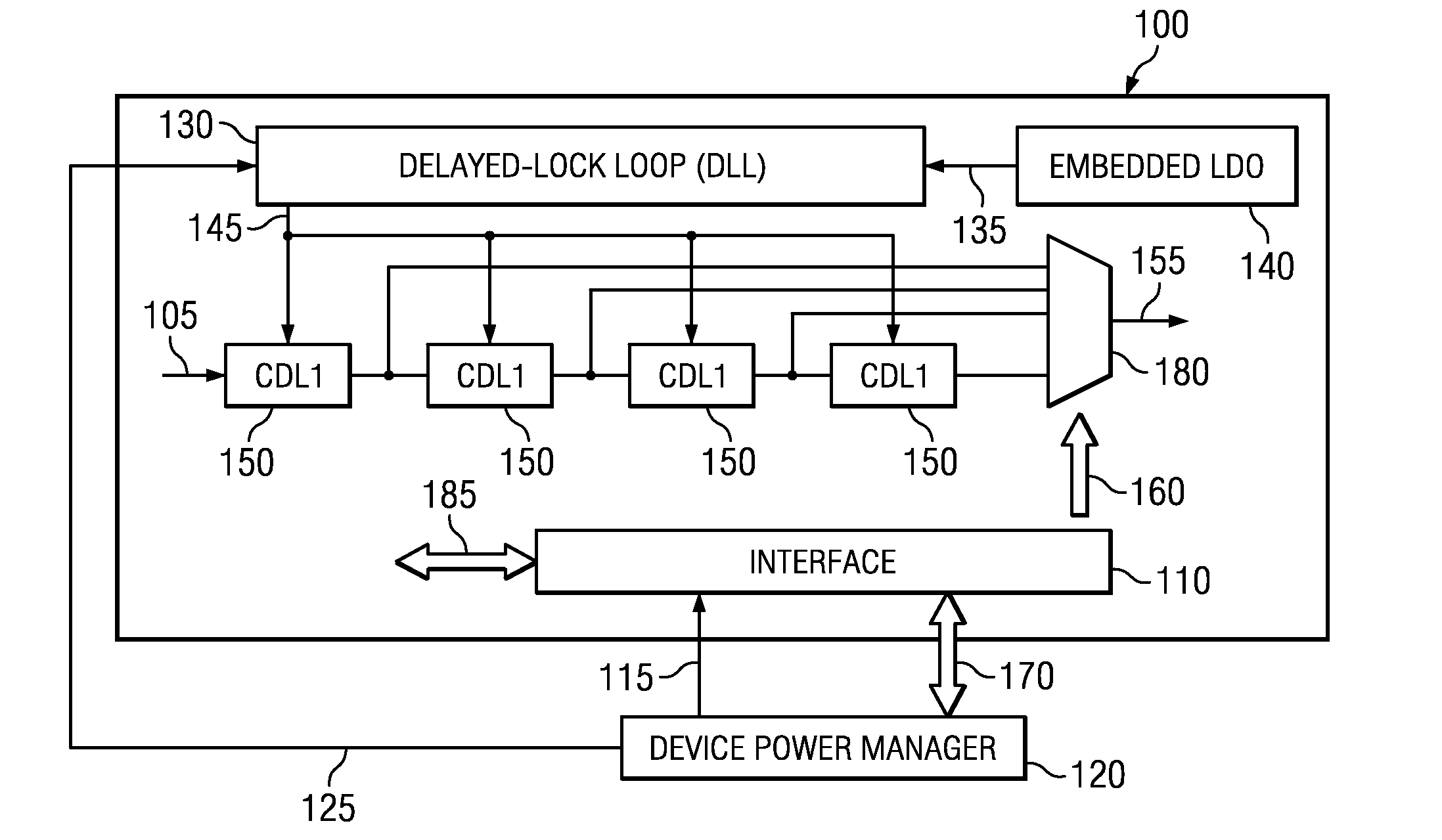
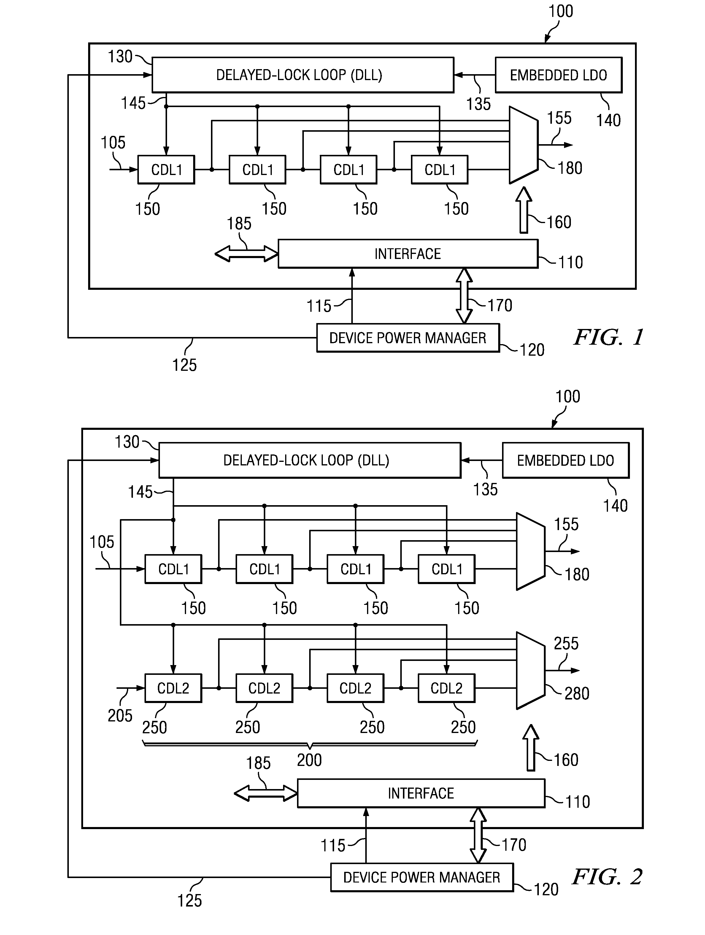
[0016]In various illustrative embodiments, as shown in FIG. 1 and FIG. 2, for example, an apparatus 100 for clock and voltage scaling on an interface 110 may comprise a device power manager 120 coupled to the interface 110 and arranged to supply a scalable frequency clock 115 to the interface 11...


PUM


Abstract

An apparatus for clock / voltage scaling includes a device power manager arranged to supply a scalable frequency clock to an interface; a delay-locked loop, supplied by a constant fixed frequency clock and a constant voltage, arranged to generate a unique code depending on process, voltage, and / or temperature; and controlled delay line elements coupled to the delay-locked loop, arranged to generate an appropriate delayed data strobe based on the unique code. A method for a digital phase lock loop high speed bypass mode includes providing a first digital phase lock loop in a first high speed clock domain; providing a second digital phase lock loop in a second clock domain; controlling an output of a first glitchless multiplexer according to preselected settings using a device power manager synchronized locally; and controlling an output of a second glitchless multiplexer using a control logic element of the second digital phase lock loop.

Description

TECHNICAL FIELD OF THE PRESENT DISCLOSURE[0001]The present disclosure relates generally to information handling devices and systems. More particularly, the present disclosure describes an apparatus, method, and system useful for enhancement of locked loop operations including clock and voltage scaling on an interface, such as an interface that uses a double data rate or a multiple data rate, for example a chip-to-chip interface that allows connecting the interconnects of two different systems on chips, and / or for providing a digital phase lock loop high speed bypass mode.BACKGROUND OF THE PRESENT DISCLOSURE[0002]In order to reduce dynamic and static power consumption on leaky processes, devices implement dynamic voltage and frequency scaling to adapt energy to the required performance. Voltage and frequency changes impact system behavior and should be properly managed. For example, voltage and frequency changes impact delay-locked loops (DLLs) used in interfaces such as memory contr...

Claims


Application Information

Patent Timeline
Patent Type & Authority Applications(United States)
IPC IPC(8): H03L7/06
CPCH03L7/0805H03L7/22H03L7/0812
Inventor DUBOST, GILLESDAHAN, FRANCKMAIR, HUGH THOMASDUBOIS, SYLVAIN
Owner TEXAS INSTR INC
Why Eureka
Try Eureka