Absorber Assembly for an Anechoic Chamber

Inactive Publication Date: 2011-04-28
ORBIT ADVANCED TECH INC
View PDF29 Cites 12 Cited by
  • Summary
  • Abstract
  • Description
  • Claims
  • Application Information

AI Technical Summary

Benefits of technology

[0015]Several advantages are offered by the invention. The invention minimizes the level of test zone reflectivity, so as to facilitate a larger test zone. The invention extends test zone performance to include lower frequencies than otherwise achievable with similarly dimensioned anechoic chambers of conventional design. The invention minimizes chamber size and volume for a given minimum level of reflectivity and test zone

Problems solved by technology

For large aperture antennas operating at higher frequencies, this distance is very large.
However, the level of reflections from walls, floor, and ceiling increases with chamber length, thus offsetting the benefit of separation distance in many applications.
However, reflections from the chamber enclosure, even when covered by an absorbing material, negatively contribute to the uniformity of illumination within the test zone.
The echo signals via indirect paths are often reflected from the walls of the chamber, and as such could contaminate measurement

Method used


Image

  • Absorber Assembly for an Anechoic Chamber
  • Absorber Assembly for an Anechoic Chamber
  • Absorber Assembly for an Anechoic Chamber

Examples


Embodiment Construction

[0043]This application is based upon and claims priority from U.S. Provisional Application No. 61 / 181,880 filed May 28, 2009, entitled Absorber Assembly for an Anechoic Chamber, which is hereby incorporated in its entirety by reference thereto.

[0044]Reference will now be made in detail to several preferred embodiments of the invention that are illustrated in the accompanying drawings. Wherever possible, same or similar reference numerals are used in the drawings and the description to refer to the same or like pans. The drawings are not to precise scale. While features of various embodiments are separately described throughout this document, it is understood that two or more such features could be combined into a single embodiment.

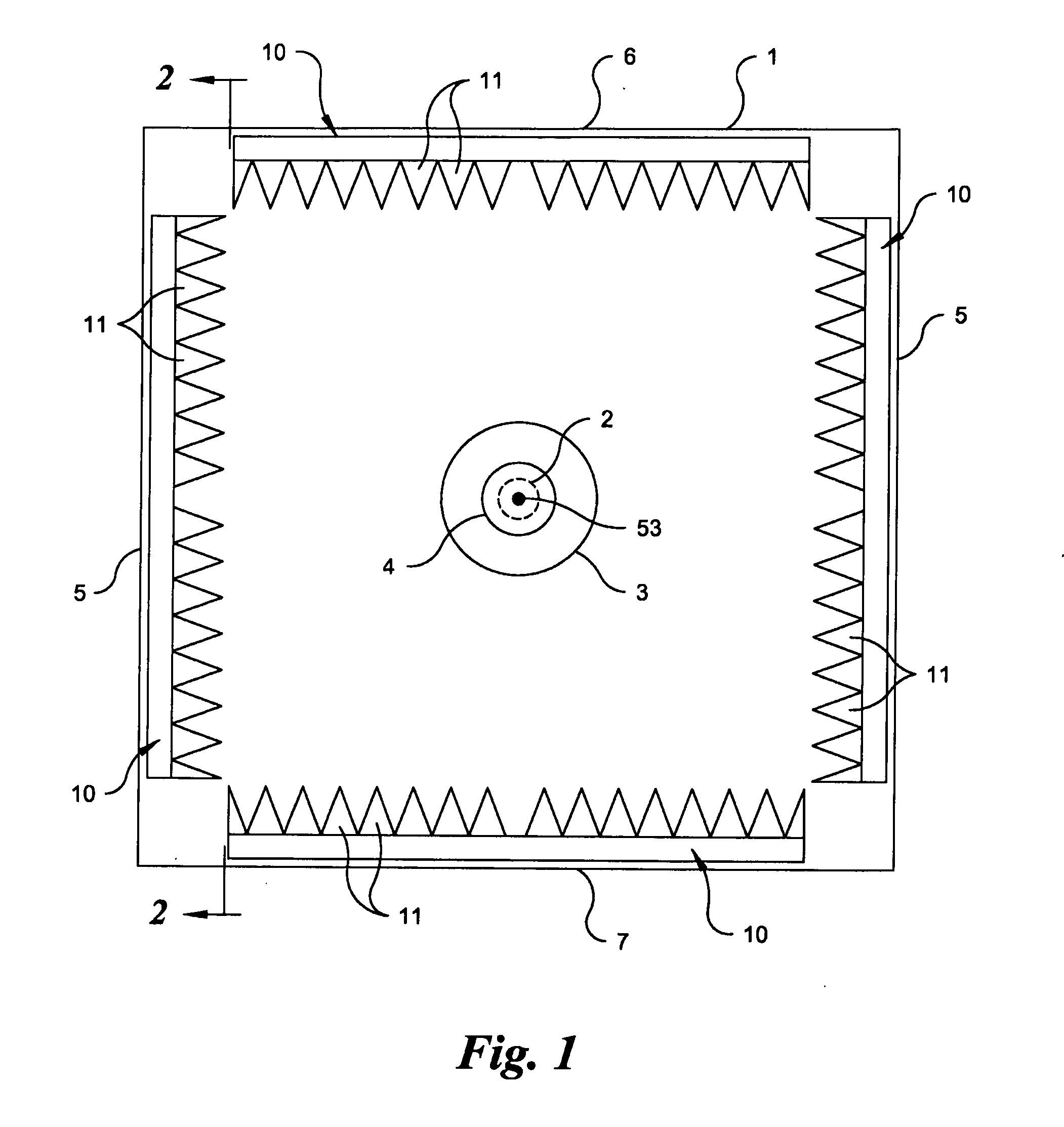
[0045]Referring now to FIG. 1, the interior of a test chamber 1 is shown from the perspective of one end showing the location and arrangement of absorber assemblies 10, a source 2, a quiet zone 3, and a test item 4. The test chamber 1 could include a varie...


PUM


Abstract

An electromagnetic absorber assembly (10) capable of minimizing reflectivity caused by reflected and diffracted waves within a test chamber (1) is presented. The absorber assembly (1) includes a plurality of first wedges (11) and a plurality of second wedges (11) disposed in a symmetrical arrangement so as to form a continuous and smoothly changing v-shaped pattern along one or more walls (5-7) of an anechoic test chamber (1). Each wedge (11) has a triangular-shaped first end (26) and second end (27) formed by a pair of side walls (16, 18, or 19) and a base wall (17). One second end (27) of each first wedge (11) contacts and covers one first end (26) of each second wedge (11) along a contact plane (15). First and second wedges (11) are disposed at a first angle (46) and a second angle (47), respectively, about the contact plane (15) in a symmetrical arrangement. The assemblies described could be installed on a flat or shaped absorber base (44) or wall (20) to divert reflected and refracted fields away from a quiet zone (3). Interplay between the shaped absorber base (44) or wall (20) and intersecting wedges (11) facilitates minimization of clutter and secondary scattering.

Description

1. TECHNICAL FIELD[0001]The invention generally relates to a device which minimizes reflectivity caused by reflected and diffracted waves within a test chamber. Specifically, the invention is a wave absorber assembly comprising a plurality of first wedge-shaped absorbers and a plurality of second wedge-shaped absorbers which are disposed so as to form a continuous and smoothly changing v-shaped pattern along the interior surface of planar or non-planar walls of an anechoic chamber. The arrangement of v-shaped absorbers improves control over reflectivity within a chamber so as to better control primary and secondary scattering effects which in turn improves quiet zone reflectivity and reduces quiet zone clutter.2. BACKGROUND ART[0002]A typical anechoic chamber for electromagnetic compatibility (EMC), far-field (FF) antenna, or radar cross section (RCS) measurements includes a metallic enclosure with internal surfaces covered by an absorbing material. An anechoic chamber also contains...

Claims


Application Information

Patent Timeline
IPC IPC(8): H01Q17/00
CPCH05K9/0001
Inventor WINEBRAND, MARKAUBIN, JOHN F.
Owner ORBIT ADVANCED TECH INC
Why Eureka
Try Eureka