Adaptive optics apparatus that corrects aberration of examination object and image taking apparatus including adaptive optics apparatus
an examination object and optics technology, applied in the field of adaptive optics apparatus, can solve the problems of insufficient correction, inability to obtain sufficient resolution, and inability to achieve uniform state of curved surface and refractive index of each tissue, so as to reduce the influence of polarization state, improve light use efficiency, and correct aberration of examination objects.
- Summary
- Abstract
- Description
- Claims
- Application Information
AI Technical Summary
Benefits of technology
Problems solved by technology
Method used
Image
Examples
embodiments
[0028]Next, embodiments of the present invention will be described.
first embodiment
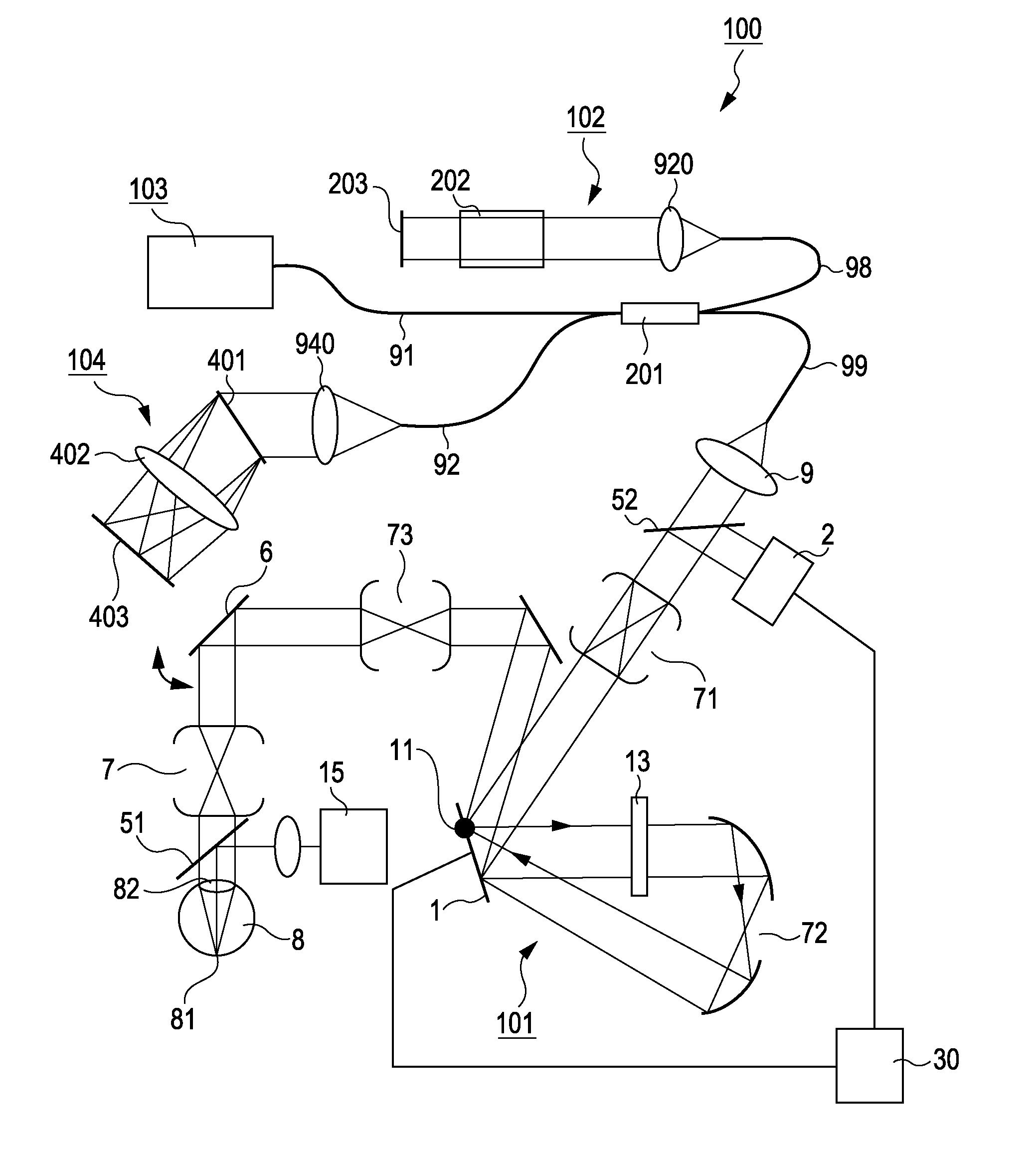
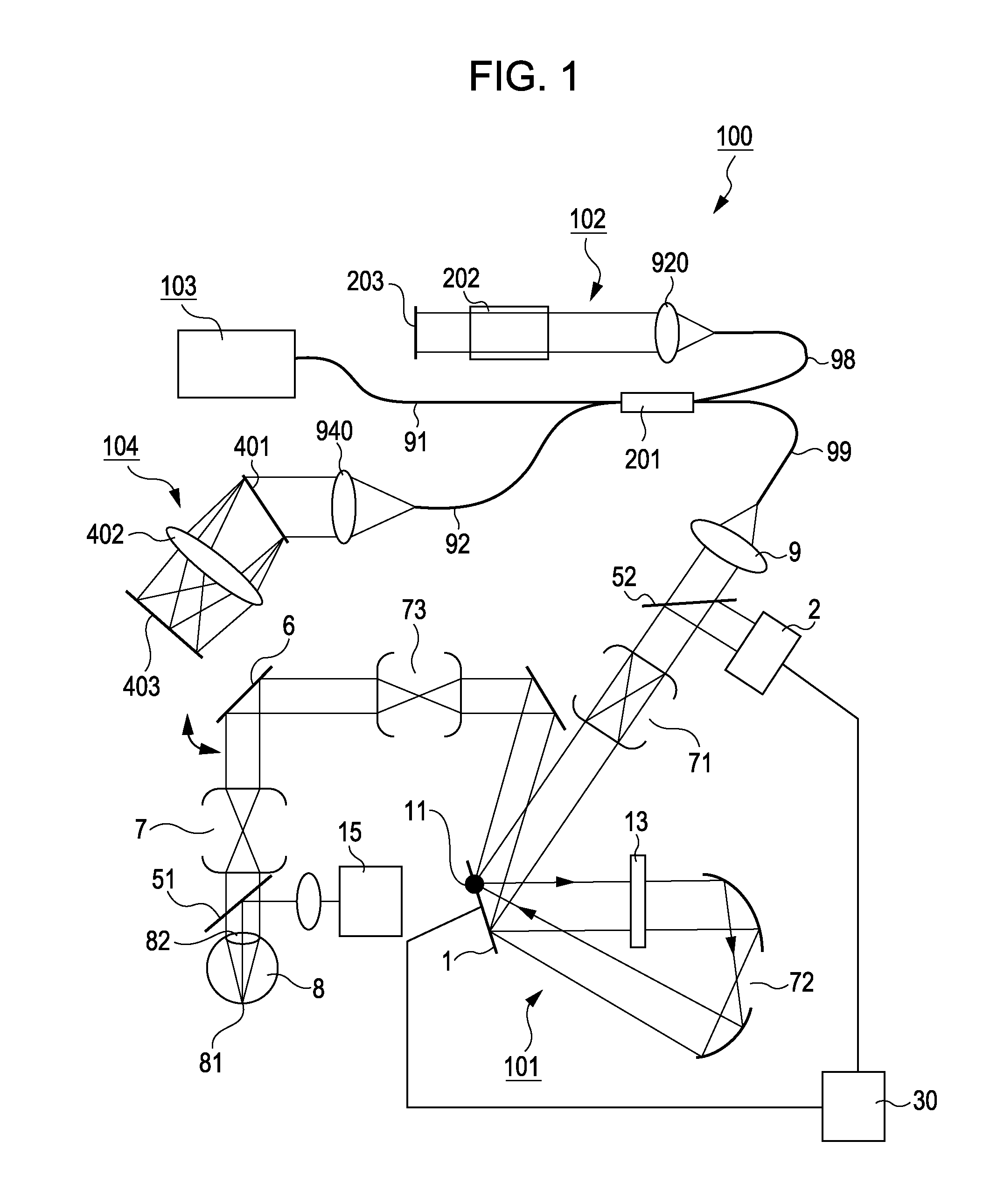
[0029]In a first embodiment, with reference to FIG. 1, a description will be given of an optical image taking apparatus (an OCT in this embodiment) that examines a fundus to which the present invention is applied. The OCT of this embodiment is an SD-OCT (Spectral Domain OCT) including an observation system 101, a reference system 102, a light source 103, and a spectrometer 104. An SLD that emits light having a wavelength of 850 nm, which is poorly absorbed and poorly scattered by components of an eye, is used as the light source 103. Light emitted from the light source 103 propagates through a single-mode fiber 91 and is split by a coupler 201 into measurement light and reference light. The measurement light propagates through a fiber 99 to the observation system 101, and the reference light propagates through a fiber 98 to the reference system 102. After going out of the fiber 99 and being imaged onto the retina 81 of an eye 8 through an optical system of the observation system 101...
second embodiment
[0034]In a second embodiment, with reference to FIG. 5, a description will be given of an optical image taking apparatus (an SLO in this embodiment) to which the present invention is applied. In FIG. 5, the same reference numerals are used to designate basically the same components as those in FIG. 1. In the first embodiment, a light source that emits light for aberration measurement is separately provided. In this embodiment, illumination light (measurement light) for fundus examination is also used as wavefront aberration measurement light. In the SLO of this embodiment denoted by reference numeral 110 in FIG. 5, illumination (measurement) light from a light source (not shown) is coupled into a single-mode fiber 99, propagates therethrough, becomes diverging light after going out of the exit end, is collimated by a collimator lens 9, and passes through a branch member 52. The core diameter of the fiber is 5 μm, the focal length of the collimator lens is about 10 mm, and the diamet...
PUM
 Abstract
Description
Claims
Application Information
 - R&D
- Intellectual Property
- Life Sciences
- Materials
- Tech Scout
- Unparalleled Data Quality
- Higher Quality Content
- 60% Fewer Hallucinations
Browse by: Latest US Patents, China's latest patents, Technical Efficacy Thesaurus, Application Domain, Technology Topic, Popular Technical Reports.
© 2025 PatSnap. All rights reserved.Legal|Privacy policy|Modern Slavery Act Transparency Statement|Sitemap|About US| Contact US: help@patsnap.com


