

Optical film composite
Inactive Publication Date: 2011-04-28
ETERNAL MATERIALS CO LTD
View PDF12 Cites 27 Cited by
- Summary
- Abstract
- Description
- Claims
- Application Information
AI Technical Summary
Benefits of technology
[0010]The optical film composite of the present invention has a light uniformization effect, is capable of effectively diffusing the light, eliminating the non-uniform brightness (mura) phenomenon, thereby providing a high imaging quality.
Problems solved by technology
In a direct type back light module, the lamps are disposed in parallel under the liquid crystal panel, and if the light is not suitably diffused and uniformized suitably, obvious lamp contour is easily caused on the display screen due to non-uniform distribution of light intensity, and thus the imaging quality is reduced.
Furthermore, the higher the demand on brightness is, or the larger the size of the display is, the higher the number of the lamps that are needed is, and the more serious the emerged mura phenomenon is.
Therefore, it becomes a major bottleneck in development in the field of LCD.
However, by this manner, the number of the LEDs is significantly increased, such that the overall cost is increased, and excessively heat is generated, and thus the service life and quality of other components are impacted.
Meanwhile, the power consumption is high, so that the requirements for batteries to provide power by many portable devices cannot be met.
Furthermore, the direct type LED back light module uses the local dimming technology, and thus being more power saving, and meeting the environmental protection requirements; however, in order to eliminate the hot spot effect, the distance between the light source and the film sheet needs to be increased so as to provide an adequate light mixing distance, and as a result, the thickness of the back light module is increased, which is not of benefit to the demand of lightening and thinning of the displays.
Method used
View moreImage
Smart ImageViewing Examples

Examples
example 1 (
E1)
[0103]The brightness enhancement element 1 was disposed above the light diffusion element 1, with the optical structure layer of the brightness enhancement element 1 facing a direction opposite to the lamps.
example 2 (
E2)
[0104]The brightness enhancement element 2 was disposed above the light diffusion element 1, with the optical structure layer of the brightness enhancement element 2 facing the direction opposite to the lamps.
example 3 (
E3)
[0105]The brightness enhancement element 3 was disposed above the light diffusion element 1, with the optical structure layer of the brightness enhancement element 3 facing the direction opposite to the lamps.
Login to View More PUM
| Property | Measurement | Unit |
|---|---|---|
| Thickness | aaaaa | aaaaa |
| Thickness | aaaaa | aaaaa |
| Thickness | aaaaa | aaaaa |
Abstract
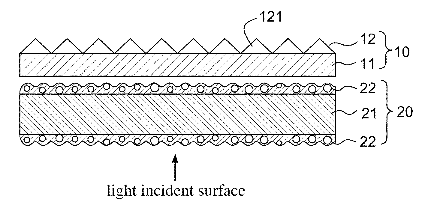
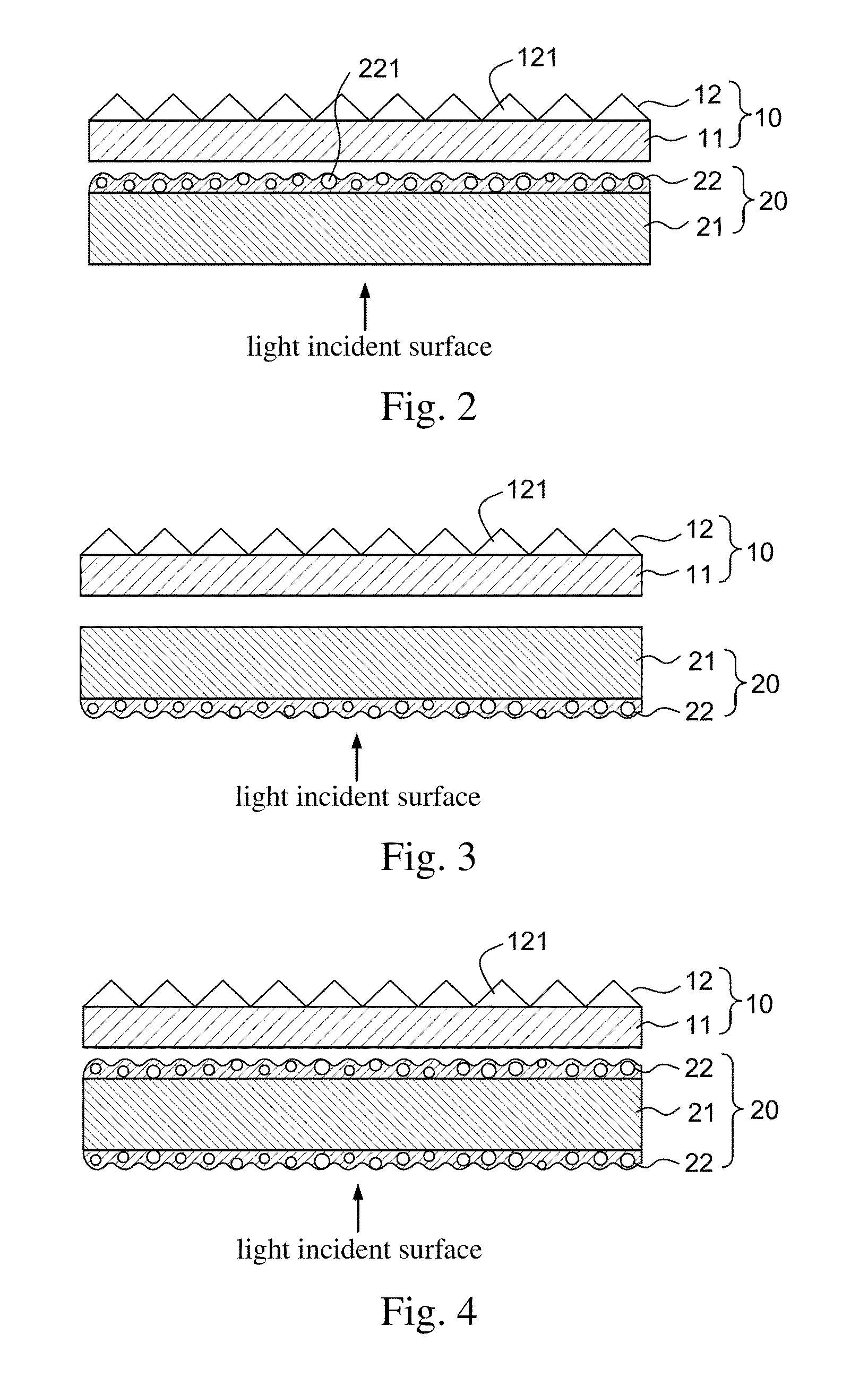
The present invention relates to an optical film composite, which comprises a brightness enhancement element and a light diffusion element, wherein the light diffusion element comprises a substrate with a light diffusion layer on at least one side thereof, wherein the light diffusion element has a haze of no less than 98% as measured according to JIS K7136 standard method.
Description
BACKGROUND OF THE INVENTION[0001]1. Field of the Invention[0002]The present invention relates to an optical film composite, and in particular, to an optical film composite applicable in a direct type back light module, especially a direct type LED back light module.[0003]2. Description of the Prior Art[0004]Liquid crystal displays (LCDs) have advantages of high image quality, low radiation, low power consumption, and good space utilization, and thus gradually replace the existing cathode-ray tube (CRT) display and become popular in the market. The main structure of the LCD includes two parts, that is, a liquid crystal panel and a back light module. As the liquid crystal panel does not emit light, the back light module is required to provide a light source needed for displaying images by the LCD, to enable the LCD to display images normally.[0005]One of commonly used light sources of the back light module is a cold cathode fluorescent lamp (CCFL). In a direct type back light module, ...
Claims
Login to View More Application Information
Patent Timeline
 IPC IPC(8): G02B5/02
CPCG02B1/04G02F2001/133507G02F1/133606G02F1/133507
InventorSUN, YU-MINGCHEN, SHIH-JUNGLIAO, CHIN-YICHEN, PEI-HSIN
OwnerETERNAL MATERIALS CO LTD