Modular power distribution and control system

a power distribution and control system technology, applied in the direction of connection contact material, coupling device connection, instruments, etc., can solve the problems of increasing labor costs, increasing the associated cost of electrical power wiring of a structure, and a rather intensive schedule of completion of installation quality, so as to minimize electromagnetic emissions, ensure quality, and ensure the effect of quality

Inactive Publication Date: 2008-11-27
BRAUNSTEIN ZACHARY L
View PDF2 Cites 32 Cited by
  • Summary
  • Abstract
  • Description
  • Claims
  • Application Information

AI Technical Summary

Benefits of technology

[0019]Only standard, agency approved, pre-assembled, tested, and inspected Modules could be used, without a single custom-made wire on outside, or a custom connection required. All components and Modules could be assembled at the factory with required level of automation to ensure repeatable quality for every installation regardless of size, complexity, location or time schedule. All components and Modules could be agency pre-approved. All pre-assembled Modules could be tested to the highest safety levels, including hi-pot, etc. Since the proposed technology could utilize described in this application Plug-n-Power methods, and together with Power-Safe or Plug-n-Safe Interfacing, based on standard cables instead of individual wires, the entire installation could be significantly safer and more reliable compared to any existing methods. As required, a section of a system or an entire system, consisting of modules, devices and components, could be shielded to isolate the environment from power related electromagnetic interferences, and result, could improve operating environment for other devices, as well as reduce safety health hazard on individuals near by. As required, a section or an entire system could be designed to confirm with respective environmental conditions. All existing power control, switching schemes, together with a new requirements, could be implemented via standardized Modules, which could be assembled-tested-inspected individually, and then inter-connected as required to implement the desired switching combination, and tested-inspected at the factory, prior for shipping as a kit to an installation location with clear instructions for ease of installation.
[0036]In addition, MPD&CS could employ respective technologies in conducting required Power Monitoring and self-diagnostics of respective components with an objective to alarm the users of possible degradation of: device, component, connection, etc. which could negatively impact the operating electrical costs due to: excessive energy consumption, process costs due to device malfunction, etc. These intelligent components or Modules could be set or programmed to disconnect a device or number of devices, which have exceeded one or more of monitored power parameters, such as: power consumption, power factor, power quality, etc., to avoid the negative impact of a potentially faulty device on business performance.

Problems solved by technology

As result, overall quality of each practical installation is at a mercy of an installation crew, which must maintain required: workmanship skills; detailed attention to specifications, including wiring diagrams, which are more complex these days due to demands for larger and sophisticated structures; installation quality at a rather intensive schedule of completion; etc.
In addition to problems stated above, the associated costs of electrical power wiring of a structure—is constantly going up, not so much due to better quality of materials, but rather due to increases in labor costs.
These re-building projects, which should be completed as soon as possible, could not afford, for example, extra expenses associated with paying high rates for expediting installations of electrical power.
While the costs of building materials in general went up significantly, and while the buildings themselves have appreciated substantially, the existing electrical components and technology used for wiring electrical power has remained disproportionably behind.
The existing technology is utilizing primarily individual wires, not cables, and as result, it would be rather challenging to reduce electromagnetic interferences produced by power devices and propagated along these wires, which could: present health risks to individuals near by; and impact operating environment for other devices.
The existing technology places a burden on an installer to implement a required load switching scheme.
Some of the switching schemes could be rather complicated, and as result, have a higher risk of mistake made by installer, which may not be discovered by installation inspector, and those impacting the quality and safety of an installation.
The existing power entry methods, although being adequate in electrical power ratings, are not conveniently packaged to provide cost-efficient power entry from outside power source to the main device and then power distribution within the main device to secondary devices.
As a result, designers of main devices have little choice, but to employ a number of off-the-shelf individual components, such as: power inlet, power protection, etc. interfaced via custom wiring, packaged in custom housings, etc., which potentially could create unnecessary challenges in meeting respective safety agency requirements, such as UL, and others.
In addition, any “in-house” custom wiring of power components within or outside a device, due to possible lack of solid quality control procedures, which, in contrast, are enforced on off-the-shelf components, could represent a potential safety hazard for individuals responsible for device operation and maintenance.
The existing power entry and distribution methods for a number of devices do not provide convenient power monitoring and diagnostics to ensure the respective device(s) performance has not degraded below projected levels, which if not noticed and then timely attended to by conducting required maintenance, etc., could costs the user of the device in terms of: higher energy costs, potential loss of a device, etc.
The existing power entry and distribution methods do not provide a cost efficient solution to the growing demands for devices aimed at automating a number of businesses, such as: grocery, retails, etc.

Method used


Image

  • Modular power distribution and control system
  • Modular power distribution and control system
  • Modular power distribution and control system

Examples


Embodiment Construction

Notes:

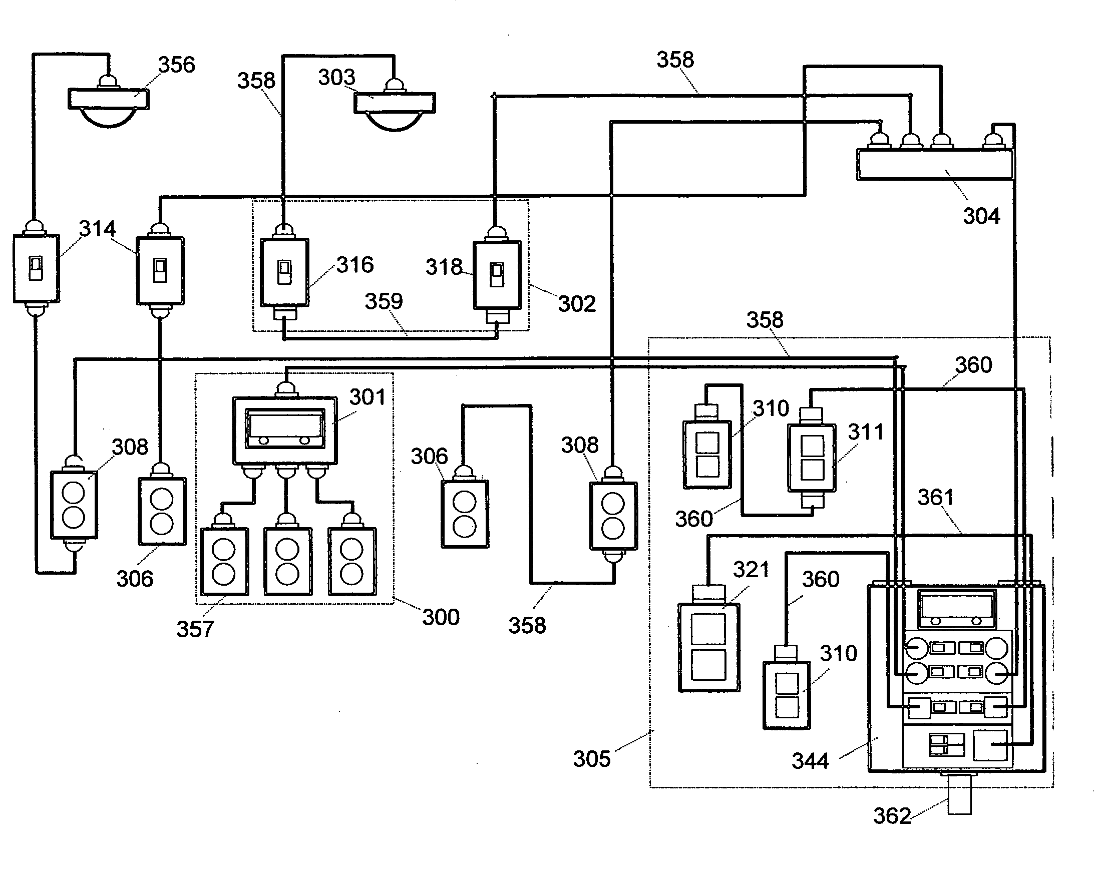
[0117]1) For simplicity, the examples of Systems, Devices, Modules and components within them, presented in document “Drawings”, are for illustration purposes of respective principals. The actual design, layout and arrangement—could be changed to meet requirements of a specific application. Although the main intent of this application is to standardize respective principals of AC power entry, distribution and control within Structures and machines, and as a result, provide off-the-shelf cost effective solutions, still—customization of various elements could be accomplished within outlined principals, to further optimize the results for any given application, while retaining the essence of Plug-n-Play, Plug-n-Power and Power-n-Safety features.

2) For simplicity, optional features, such as: component shielding, grounding, strain-relief, environmental seals, etc. are not shown on all drawings
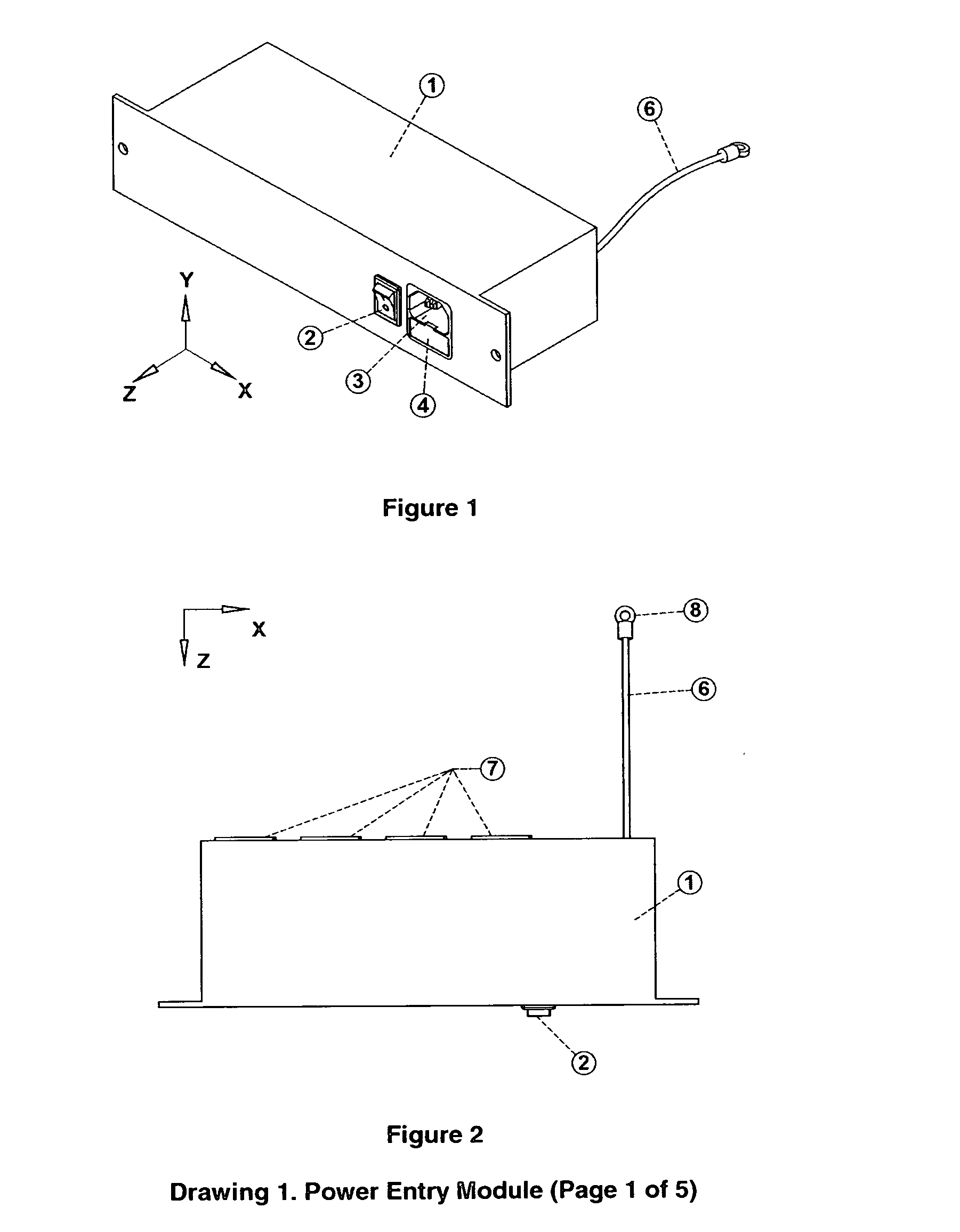
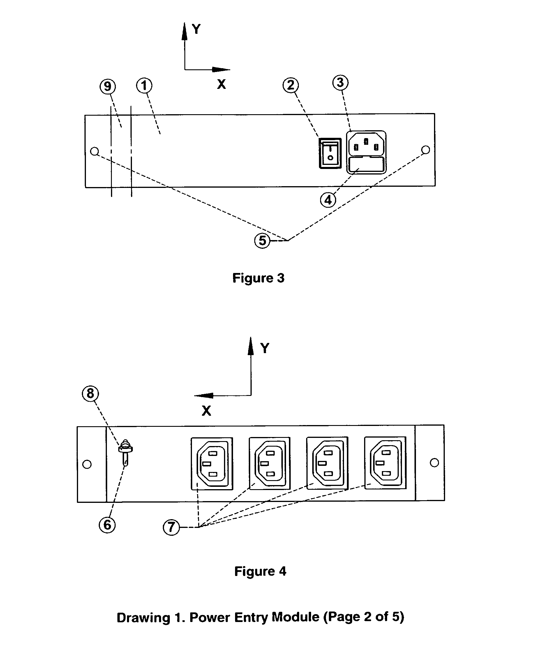
Drawing 1

5 Pages

[0118]Drawing 1 illustrates various packaging configurations of Entry Modu...


PUM

PropertyMeasurementUnit
voltageaaaaaaaaaa
electromagnetic compatibilityaaaaaaaaaa
voltageaaaaaaaaaa

Abstract

The principals and methods described in our application—provide essential tools for designing a convenient, safe, cost efficient power distribution and control system, which could become industry-standard method, benefiting: providers, users and service personnel of the system.The outlined principals, methods could effectively and efficiently support development and installation of power distribution systems for variety of projects, including: residential, commercial and industrial. In addition, the proposed methods could be used in the designs of power distribution to and within variety of electro-mechanical devices or machines.Designs based on proposed technology will outperform the existing methods in terms of its: superior reliability, safety, quality and costs.Proposed technology will help to transform the existing labor-intense installations into practically plug-n-play type of installations. For any given project, a pre-designed fabrication kit, containing newly developed, agency approved sub-assemblies and support components, as specified in our application, could be made available and delivered directly to the installation site. Kit containing a section of or an entire system could be pre-tested at the factory.The proposed technology could significantly lower the labor costs, while improving labor safety, quality and repeatability. Labor intense operations: wire crimping, outlet / switch hook-ups, etc.—could be practically eliminated during installation.Power distribution systems designed by proposed methods will offer better quality, installation and utilization safety, and lower costs. In addition, utilization of shielded cables and shielding of other components within a system, could significantly lower electrical power emissions, which could benefit the environment, and ease requirements on other technologies.

Description

CROSS-REFERENCE TO RELATED APPLICATIONS[0001]We claim the benefits of Provisional Application No. 60 / 931,792 filed on May 25, 2007, title “Modular power distribution and interface system”, and Provisional Application No. 61 / 002,964 filed on Nov. 14, 2007, title “Modular power distribution and control system”.STATEMENT REGARDING FEDERALLY SPONSORED RESEARCH OR DEVELOPMENT[0002]Not applicable.REFERENCE TO SEQUENCE LISTING, A TABLE, OR A COMPUTER PROGRAM LISTING COMPACT DISK APPENDIX[0003]Not applicable.BACKGROUND OF THE INVENTION[0004]A majority of hi-power AC electrical wiring of residential and commercial structures, as one of important steps in providing completed structure with required power, has fallen drastically behind the progress attained in other areas of construction, such as: wiring for communications, including phone lines, LAN, internet, etc. Based on existing methods of wiring AC electrical power, the installation time, installation quality, reliability, repeatability ...

Claims


Application Information

Patent Timeline
Patent Type & Authority Applications(United States)
IPC IPC(8): H02B1/00
CPCH01H2011/0093H01R13/713H01R25/006Y10T29/49169Y10T29/4913Y10T29/49004Y10T29/49105
Inventor BRAUNSTEIN, ZACHARY L.MAH, FREDERICK Y.
Owner BRAUNSTEIN ZACHARY L
Why Eureka
Try Eureka