Lathe Tool, In Particular Boring Tool

a cutting tool and boring technology, applied in the field of rotating cutting tools, can solve the problem that the core of the tool is not affected by the driver connection, and achieve the effects of optimizing the removal of chips, improving the concentric running of the tool in the bore, and good mounting of the borer body

Active Publication Date: 2011-04-28
KENNAMETAL INC
View PDF18 Cites 31 Cited by
  • Summary
  • Abstract
  • Description
  • Claims
  • Application Information

AI Technical Summary

Benefits of technology

[0031]In a first configuration, the supporting element is configured as a disk which is plane-parallel to the end faces, adjacent to one another, of borer body and borer head. This disk-shaped supporting element preferably projects like a sliding ring segment beyond the lateral surfaces of borer body and borer head and thus supports the boring tool relative to the bore wall. In this way, the course of the boring tool in the bore is stabilized, while the cutting edges in the borer head can machine the bore wall.
[0032]A further preferred embodiment of the supporting element has a ring-like integrally formed portion which overlaps the lateral surfaces either of the borer body or of the borer head or of borer body and borer head at the same time. This embodiment has the advantage that the supporting element bears like a sliding ring against a large area of the bore wall. In addition, in a bowl-like configuration of the supporting element having a basic body configured as a plane-parallel disk and an annular integrally formed portion, especially good mounting of the borer body and of the borer head in the coupling region is ensured. In a further configuration, recesses corresponding to the flutes formed in the borer body and in the borer head can be provided in the supporting element in order to optimize the chip removal. The comparatively large outer circumferential surface of the ring-like integrally formed portion on the supporting element enables the attachment of special guide elements for guiding the boring tool on the bore wall. These guide elements can be strip-shaped or bulged or can be designed in other geometries for improving the concentric running of the tool in the bore. These guide elements can be integrally embedded in the outer surface of the ring element. However, it is also possible to fix them in the ring element in a clamping manner.
[0033]In a further configuration, the supporting element can have a coating, in particular in the region of the ring-like integrally formed portion. This coating can serve to prevent the wear on the outer surface of the ring relative to the bore wall. The coating can also influence the other vibratory and transmission properties of the tool.

Problems solved by technology

As a result, the core of the tool is unaffected by the driver connection.

Method used


Image

  • Lathe Tool, In Particular Boring Tool
  • Lathe Tool, In Particular Boring Tool
  • Lathe Tool, In Particular Boring Tool

Examples


third embodiment

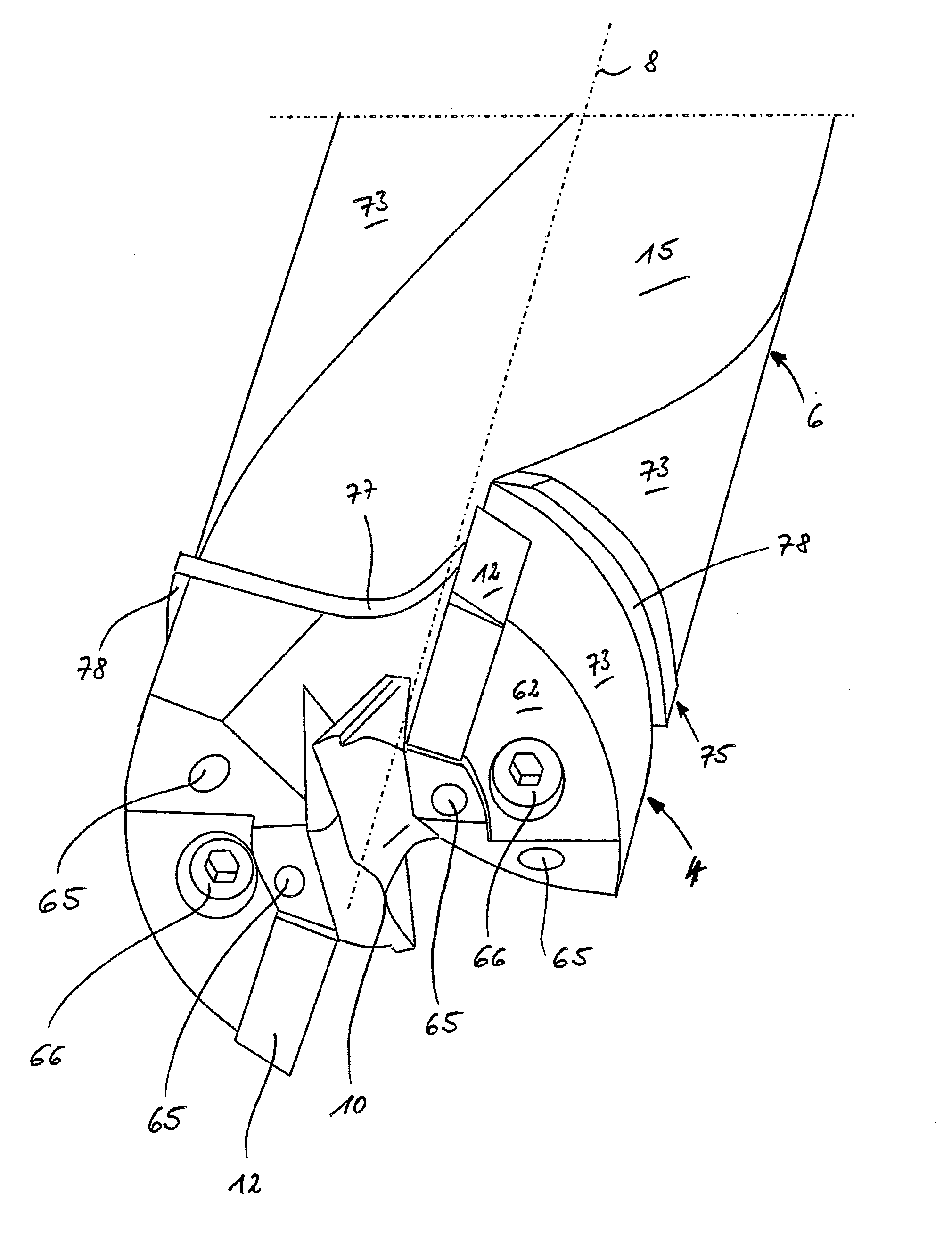
[0073]The third embodiment variant shown in FIG. 6 is based on the embodiment variant according to FIG. 5. Here, too, the left half of the figure shows the unclamped state and the right half of the figure shows the clamped state. In contrast to the exemplary embodiment in FIG. 5, a compensating element 32 is arranged in the corner region which connects the driver surfaces 30 to the outer bearing surfaces 28. The compensating element is designed like a dowel pin, extends parallel to the center axis 8 and has a circle-segment-like area as viewed in cross section. On account of the compensating element 32, that corner region of the driver pin 18 which relates thereto is of flattened design, as can best be seen from FIG. 7. At its rear end, the compensating element 32 has a cylindrical fastening shank 34, with which it is inserted into a cylindrical shank receptacle 36 (FIG. 8) in the bottom of the receiving pocket 20. The compensating element 32 is rotatable about its longitudinal axis...

first embodiment

[0076] variant, which is explained with reference to FIGS. 9a, 9b, a clamping screw 16 is passed through the borer head 4 from the front end face of the borer head 4, and this clamping screw 16 runs through the fastening bore 24 of the driver pin 18 and can be screwed into an associated fastening bore 24′, designed as a screw hole, in the receiving pocket 20. The fastening bores 24, 24′ are not arranged parallel to the center axis 8 but rather are arranged in an inclined manner. In this case, the center axis of the fastening bore 24 runs within a plane. This plane is defined by the axial direction and a clamping direction which is indicated in FIG. 9a by the arrow 37. The clamping direction 37 is in this case defined by the direction in which the driver pin 18 is clamped against the receiving pocket 20. The clamping direction is in this case preferably oriented perpendicularly to the driver surface 30. With regard to a line running in this plane parallel to the center axis 8 (and th...

second embodiment

[0081]The second embodiment variant of the clamping device will now be explained in more detail with reference to FIGS. 12 to 14. In FIG. 13, the unclamped state between the two coupling elements is again indicated in the left half of the figure and the clamped state is indicated in the right half. In this embodiment variant, the driver pin 18 additionally comprises a respective clamping pin 48 which extends in the axial direction starting from the base side. In the exemplary embodiment, the clamping pin 48 has a roughly rectangular to elliptical cross-sectional contour and is arranged eccentrically on a marginal side.

[0082]The clamping pin 48 has a frustoconical receiving opening 50 in which a clamping element 52 designed as a screw and having a likewise frustoconical point engages (FIGS. 13 and 14). Due to the frustoconical, that is to say tapering, configuration of the receiving opening 50 and of the clamping element 52, an axial force component is also generated at the same time...


PUM

PropertyMeasurementUnit
free rotation angleaaaaaaaaaa
angleaaaaaaaaaa
angle of inclinationaaaaaaaaaa

Abstract

A boring tool has a receiving part implemented as a borer body and a front part implemented as a borer head, which extend along a central axis and can be removably fastened to one another via driver connection. The driver connection has at least two coupling pairs which are separate from one another and are disposed eccentrically relative to the central axis. Each coupling pair is formed by interlocking coupling elements, namely a receiving pocket and a driver pin. The coupling elements have an asymmetrical cross-sectional area and widen with increasing distance to the central axis. Through this design, a reliable transmission of high torques is achieved with lower strains of the borer body in the area of the driver connection. Simultaneously, an automatic centering of the two tool parts to one another is performed.

Description

BACKGROUND OF THE INVENTION[0001]The invention relates to a rotating cutting tool, in particular a boring tool, comprising a receiving part and a front part which extend along a center axis and are detachably fastened to one another via a driver connection.[0002]Such a cutting tool designed as a boring tool can be seen from WO 2007 / 107294 A1. This boring tool is a modular cutting tool which has an interchangeable tool head which can be detachably connected to a fluted boring body via the driver connection. The driver connection in this case comprises a driver web arranged on the underside of the boring head and extending across a center longitudinal axis. Said driver web is inserted into a receiving pocket, corresponding to the shape of the driver web, of the boring body. The receiving pocket in this case encloses the driver web over the full circumference.[0003]The driver connection generally serves to transmit torque between the two tool parts. In such driver connections, there is...

Claims


Application Information

Patent Timeline
Patent Type & Authority Applications(United States)
IPC IPC(8): B23B51/02
CPCB23B51/02B23B2250/12Y10T408/892B23B2251/50B23B2251/70B23B2251/02Y10S408/713Y10T408/78Y10T408/907Y10T408/909Y10T408/9097Y10T408/90993
Inventor JAGER, HORST MANFREDZEUG, BERTHOLD HEINRICH
Owner KENNAMETAL INC
Why Eureka
Try Eureka