Curved composite frames and method of making the same

a composite frame and curved technology, applied in the field of composite frames, can solve the problems of complicated task of tailoring the laminated plies of the frame to meet various performance requirements, and the cost of fabricating two-piece frames is also relatively high, so as to optimize structural efficiency, reduce weight, and save labor

Active Publication Date: 2011-04-28
THE BOEING CO
View PDF60 Cites 66 Cited by
  • Summary
  • Abstract
  • Description
  • Claims
  • Application Information

AI Technical Summary

Benefits of technology

[0006]The disclosed embodiments provide a curved composite frame suitable for aircraft applications that is weight efficient and reliable, while able to control deflections and maintain airframe rigidity in the hoop direction of an aircraft fuselage. The disclosed composite frame is of a one-piece construction having an integral shear tie to which an aircraft outer skin may be attached. The frame comprises laminated composite plies including unidirectional reinforcing fibers, with ply / fiber orientations referenced to a polar coordinate system that defines the curvature of the frame. Orientation of the plies within the polar coordinate system allows the fibers within at least certain of the plies to be positioned substantially tangent to the frame curvature at substantially all points along the frame curvature. Maintaining the zero degree plies tangent to the frame curvature allows selection of laminate orientation percentages in the web, inner chord and outer chord of the frame that may increase the modulus of the frame in the hoop direction within the frame's cross section, thereby optimizing structural efficiency and reduced weight. The one-piece frame has an optimized cross sectional shape that allows integration of a shear tie into the frame.

Problems solved by technology

Moreover, laminate ply layout is performed using a moving Cartesian coordinate reference which complicates the task of tailoring the laminated plies of the frame to meet various performance requirements, including strength, rigidity and weight.
Also, two-piece frames are also relatively expensive to fabricate because of the hand labor needed to assemble the pieces, and additional material requirements, including multiple fasteners.

Method used


Image

  • Curved composite frames and method of making the same
  • Curved composite frames and method of making the same
  • Curved composite frames and method of making the same

Examples


Embodiment Construction

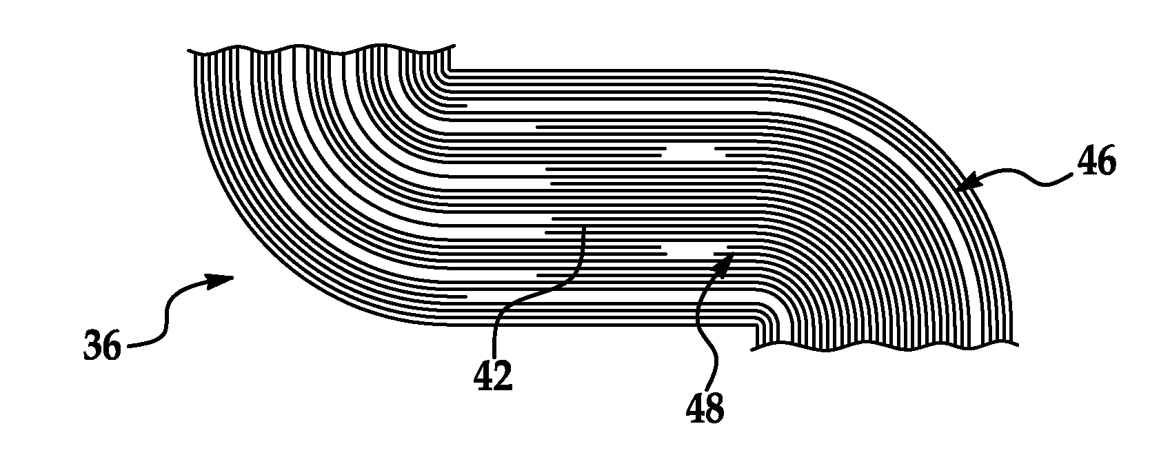
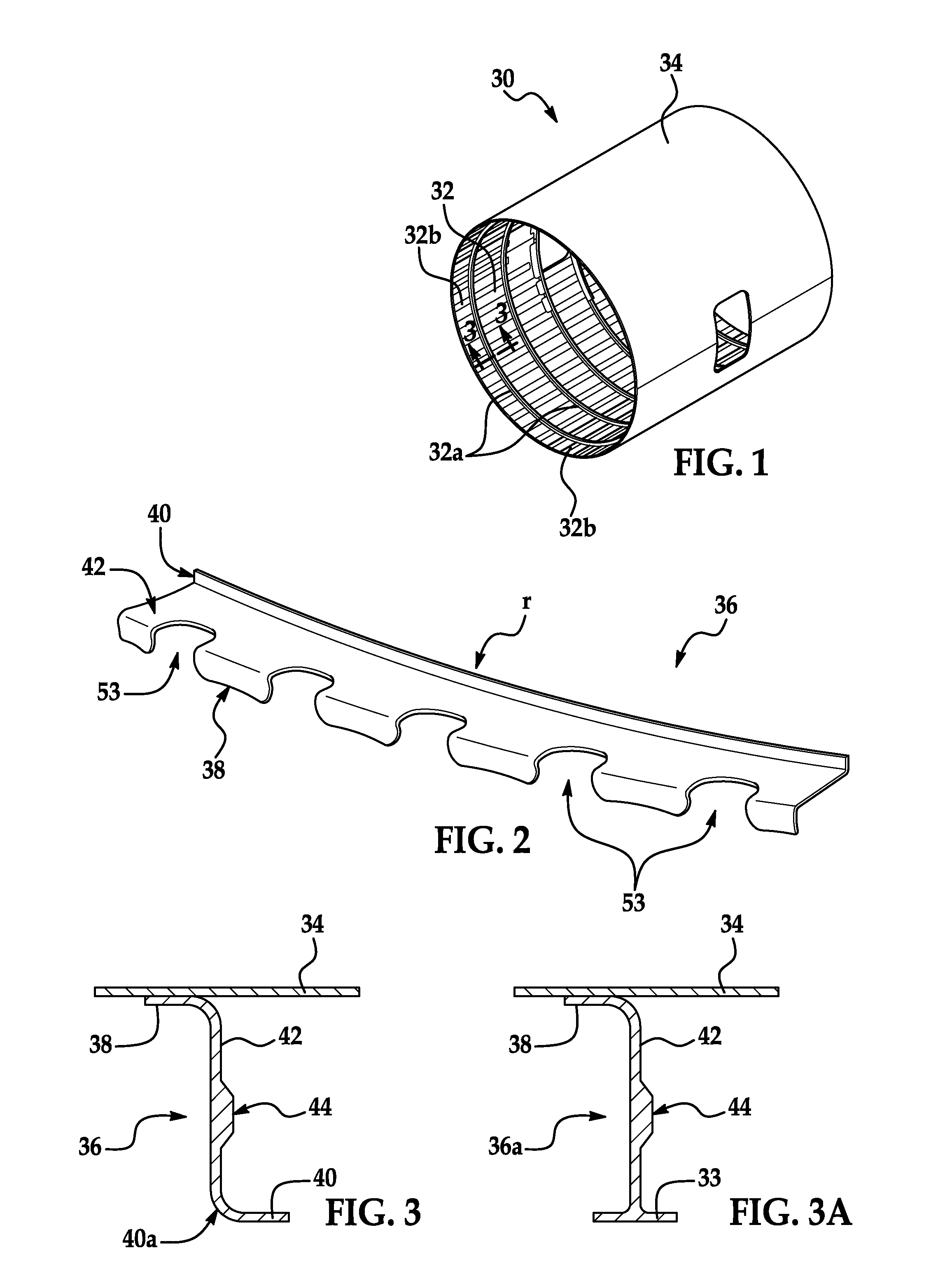
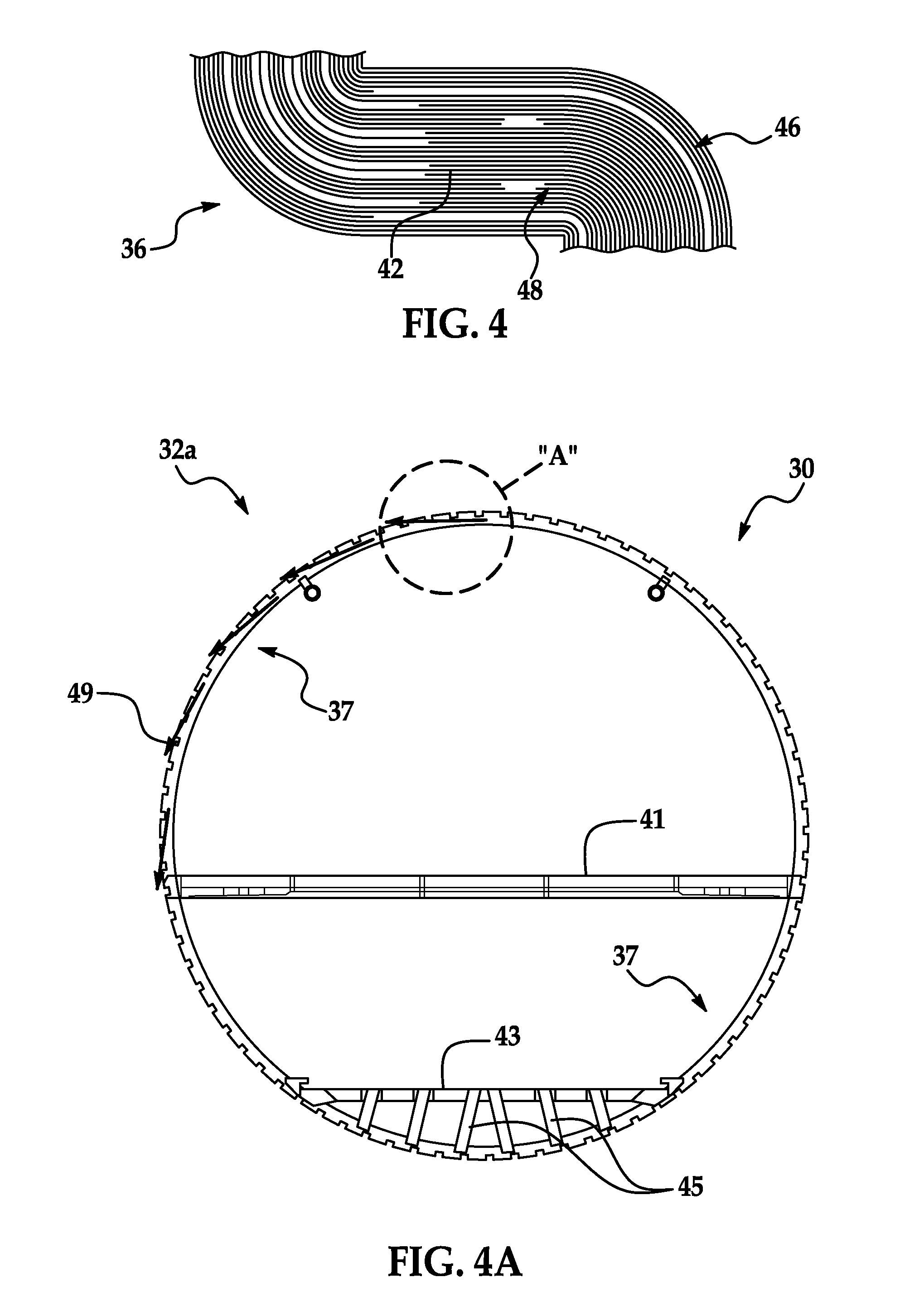
[0049]Referring first to FIGS. 1-3, a barrel shaped fuselage section 30 comprises an outer skin 34 formed over and fastened to a frame structure 32. The frame structure comprises a plurality of longitudinally spaced, barrel frames 32a and longitudinally extending stringers 32b which pass through the barrel frames 32a. Each of the barrel frames 32a may comprise multiple, one-piece frame sections 36 that are spliced together using any suitable means, such as without limitation, splice plates (not shown) and fasteners (not shown). In some applications however, half frame and full frame sections (not shown) may be possible. While the barrel shaped frame 32a are shown in the illustrated embedment as being substantially circular, other frame shapes are possible, including, for example and without limitation, oval or piecewise-circular or other non-circular shapes that have one or more contours or curvatures. As used herein, the terms “contour” and “curved” or “curvature” are used intercha...


PUM

PropertyMeasurementUnit
polar angleaaaaaaaaaa
widthaaaaaaaaaa
widthaaaaaaaaaa

Abstract

A curved composite aircraft frame comprises a multi-ply composite laminate having a generally Z-shaped cross section. At least certain of the laminate plies include unidirectional reinforcing fibers that are substantially tangent at substantially all points along the curvature of the frame.

Description

CROSS REFERENCE TO RELATED APPLICATIONS[0001]This application is a continuation-in-part of co-pending U.S. patent application Ser. No. 12 / 396,418 filed Mar. 2, 2009, which is a continuation-in-part of co-pending U.S. patent application Ser. No. 12 / 104,529 filed Apr. 17, 2008, the entire disclosures of which applications are incorporated by reference herein.TECHNICAL FIELD[0002]This disclosure generally relates to composite structures such as airframe components, and deals more particularly with a curved, one-piece composite frame section for an aircraft fuselage having an integral shear tie, and a method for making the same.BACKGROUND[0003]Highly contoured, multi-leg structures having high strength and lightweight may be used in various applications, such as in aerospace vehicles. A variety of frames and similar structures used in aerospace applications may have legs which are highly curved or contoured along the length of the structure. For example, hoop shaped frame sections for a...

Claims


Application Information

Patent Timeline
Patent Type & Authority Applications(United States)
IPC IPC(8): B32B1/00B23P17/00B23P11/00
CPCB29C70/207B29C70/30B29C70/38B29L2031/3082B64C1/064Y10T428/24628Y02T50/433B64C2001/0072Y10T29/49801Y10T29/49826Y10T29/49622B64C1/061B29D99/0003Y02T50/40B29C70/304
Inventor KEHRL, DAVID J.JOHNSON, KENT E.MCCARVILLE, DOUGLAS A.
Owner THE BOEING CO
Why Eureka
Try Eureka