Battery pack with precise dimensions

a battery cell and precise technology, applied in the field of batteries, can solve problems such as projection deformation and squashing, and achieve the effect of suppressing the effect of variation in battery cell dimensions and high-precision dimensions

Inactive Publication Date: 2011-04-28
SANYO ELECTRIC CO LTD
View PDF1 Cites 4 Cited by
  • Summary
  • Abstract
  • Description
  • Claims
  • Application Information

AI Technical Summary

Benefits of technology

is to suppress the effects of variation in battery cell dim...

Problems solved by technology

Consequently, during battery pack assembly, when the circuit board holder is pressed against the end-plane of ...

Method used


Image

  • Battery pack with precise dimensions
  • Battery pack with precise dimensions
  • Battery pack with precise dimensions

Examples


first embodiment

1.Battery pack 1 external structure

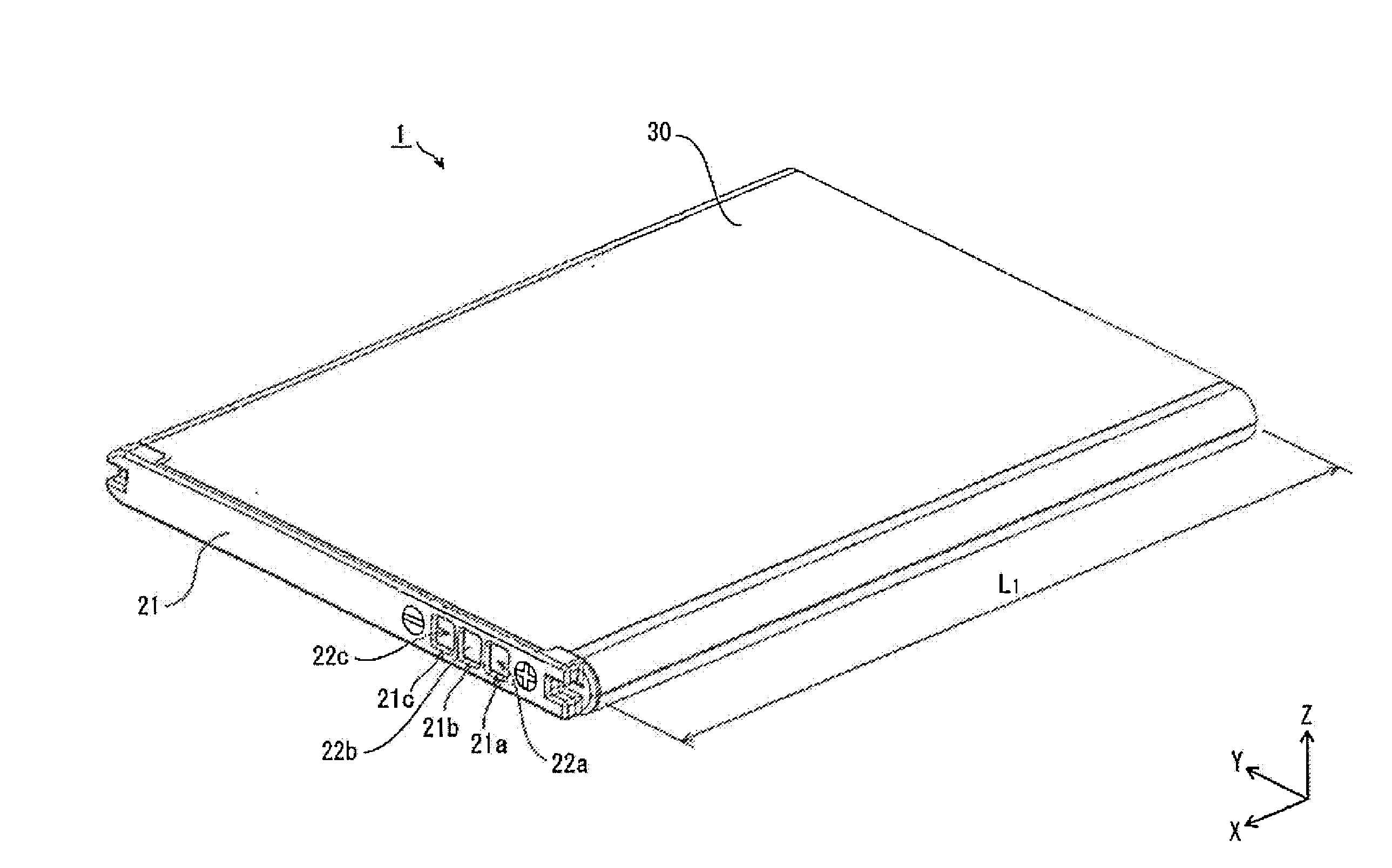
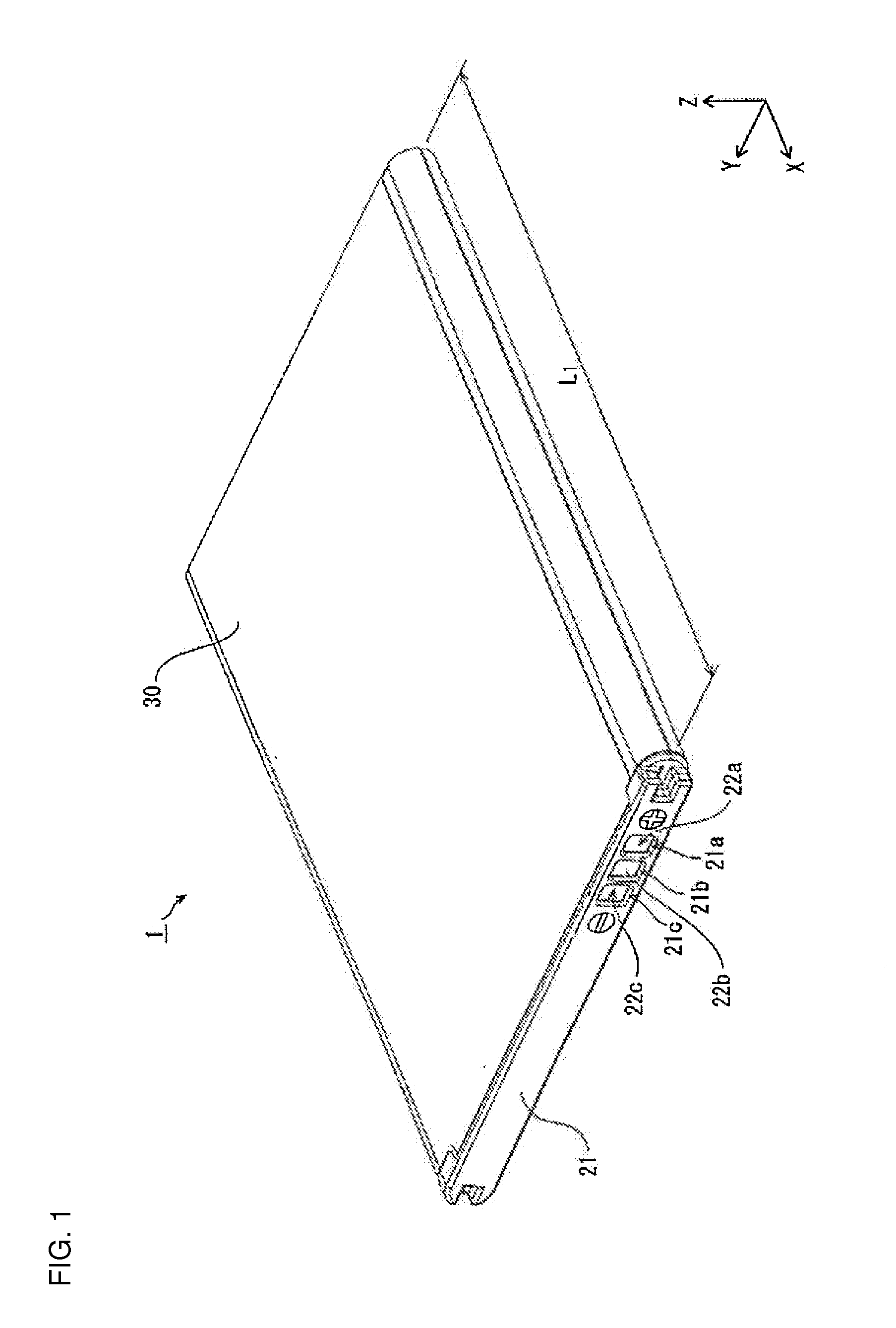
As shown in FIG. 1, the battery pack 1 for the first embodiment of the present invention has an external structure that includes a cap 21 disposed at the left-front on the X-axis, a bottom cover (not illustrated in FIG. 1) disposed at the right-rear on the X-axis, and an outer label 30 that covers the perimeter surfaces.

The cap 21 is provided with three windows 21a-21c, and external connecting terminals 22a-22c are exposed to the outside through those windows 21a-21c. The outer label 30 also covers part of the perimeter surfaces of the cap 21 and the bottom cover.

2.Battery pack 1 internal structure

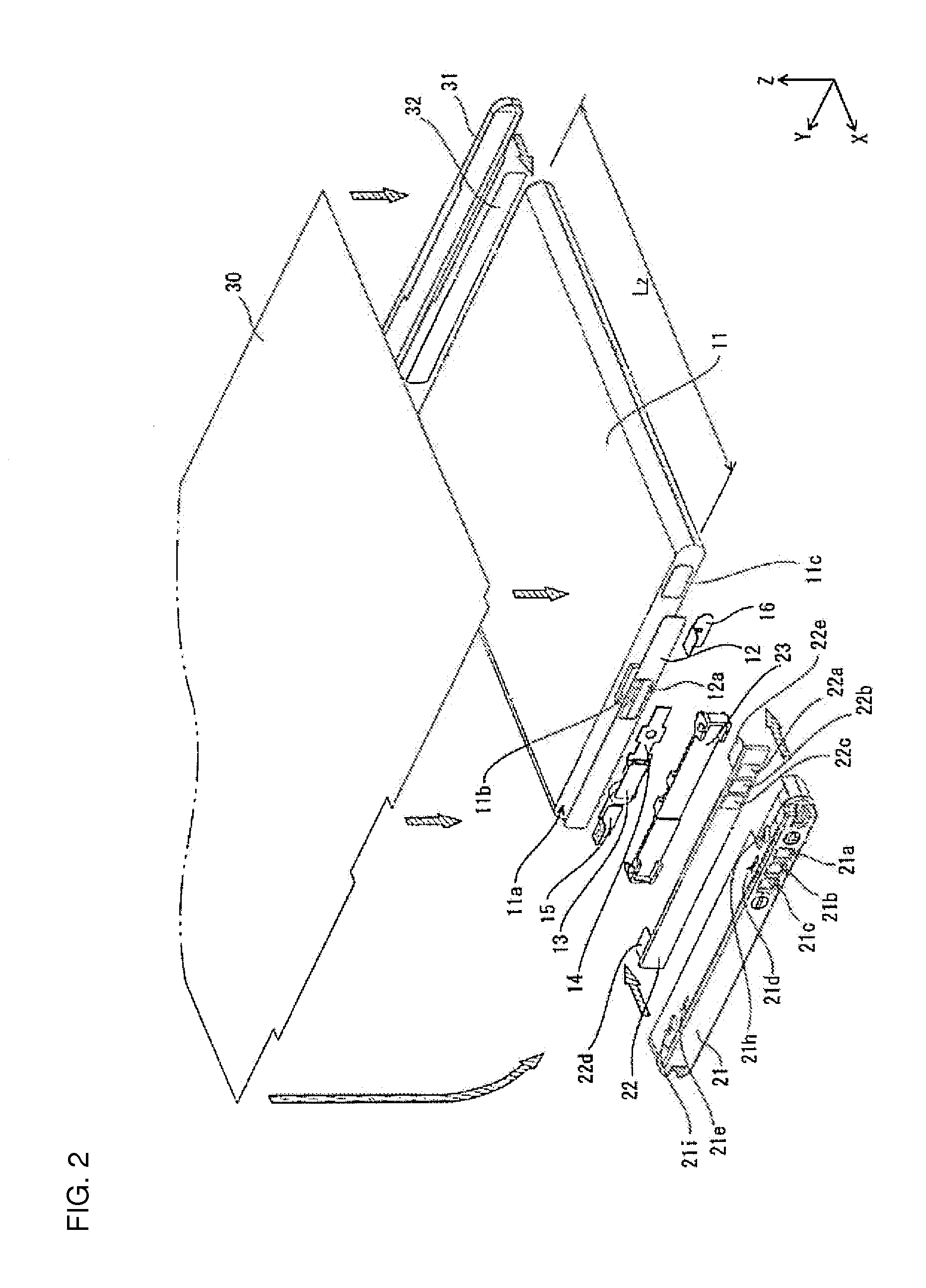
As shown in FIG. 2, the battery pack 1 for the first embodiment of the present invention has a battery cell 11 with a flat solid rectangular external shape, and a positive temperature coefficient (PTC) device 13 and circuit board 22 disposed along the battery cell 11 end-plane 11 a at the left-front on the X-axis.

A lead-plate 14 and another lead-plate 15 ...

second embodiment

FIGS. 9 and 10 are used to describe the structure of the battery pack 2 for the second embodiment of the present invention. Here, description of structures common to the battery pack 1 for the previously described first embodiment is abbreviated, and emphasis is placed on the description of elements that are different.

1. Cap unit 40 structure

As shown in FIG. 9, the cap unit 40 for the second embodiment is configured as an assembly of a cap 41 and a circuit board 42 with the circuit board holder eliminated. Specifically, the cap 41 is provided with rectangular holes 41d, 41e, 41f, 41g through the side-wall surfaces. Further, the cap 41 has two projections 41l . . . (only one projection 41l is shown in FIG. 9) on the inside of the cap 41 at both ends along the Y-axis that extend towards the right-front along the X-axis.

The circuit board 42 is provided with two circuit board lead-plates 42d, 42e on a primary surface at the right-front along the X-axis. Further, locking pieces 42f, 42g,...


PUM


Abstract

The battery pack has a battery cell 11, a circuit board 22 disposed along one end-plane 11a of the battery cell 11,and a circuit board holder 23 that intervenes between the circuit board 22 and the battery cell 11 end-plane 11a. The circuit board holder 23 is provided with a main body that holds the circuit board 22 and four projections 23h-23k protruding towards the end-plane 11a of the battery cell 11 (in the negative direction along the X-axis). Further, the projections 23h-23k on the circuit board holder 23 have lower mechanical strength than the main body and function as buffers to absorb dimension variation in the battery cell 11. Specifically, the end regions of the projections 23h-23k that contact an insulating board 12 disposed on top of the battery cell 11 end-plane 11a are squashed down by just an amount to absorb the battery cell 11 dimension variation.

Description

BACKGROUND OF THE INVENTION1. Field of the InventionThe present invention relates to a battery pack, and in particular relates to a battery pack structure to improve the accuracy of battery pack dimensions upon completion of fabrication.2. Description of the Related ArtA battery pack is used as a power source in mobile electronic devices such as cellular (mobile) telephones (Refer to Japanese Patent No. 3668195 and Japanese Laid-Open Patent Publication 2006-66290). FIG. 11 is used to describe an example of the structure of a prior art battery pack. As shown in FIG. 11, a prior art battery pack has a battery cell 911 with a flat solid rectangular external shape, and a PTC (positive temperature coefficient) device 913 and circuit board 922 disposed along a battery cell 911 end-plane 911a at the left-front along the X-axis of the figure. The PTC device 913 is connected via a lead-plate 914 to the negative electrode terminal 911b that protrudes out from the battery cell 911 end-plane 91...

Claims


Application Information

Patent Timeline
IPC IPC(8): H01M2/00H01M2/04H01M50/55H01M50/553H01M50/555H01M50/591
CPCH01M2/0215H01M10/0525H01M2/34H01M2/30Y02E60/10H01M50/555H01M50/553H01M50/55H01M50/591H01M50/50H01M50/20
Inventor NAMURA, TAKASHI
Owner SANYO ELECTRIC CO LTD
Why Eureka
Try Eureka