Intraocular lens and manufacturing method thereof

a manufacturing method and lens technology, applied in the field of intraocular lenses, can solve the problems of difficulty in folding the lens, thicker optical parts, and subsequent complications of secondary cataracts

Inactive Publication Date: 2011-04-28
KOWA CO LTD
View PDF4 Cites 26 Cited by
  • Summary
  • Abstract
  • Description
  • Claims
  • Application Information

AI Technical Summary

Benefits of technology

With the foregoing in view, it is accordingly an object of the present invention to provide an intraocular lens of novel design whereby sufficiently large size of the effective optical part is assured, while also affording excellent ability to inhibit the development of secondary cataracts.
The scientific grounds as to why the use of a laser beam having a pulse width of between 1×10⁻¹⁶ second and 1×10⁻⁷ second is advantageous for producing the minute linear grooves and lands is poorly understood, nor is it an object of the invention to shed light upon such scientific grounds; however, when a laser beam of pulse width between 1×10⁻¹⁶ second and 1×10⁻⁷ second directed onto a machining face is scattered at the surface of the machining face, surface scattered light is produced. Through ablation arising in sections of interference of this surface scattered light with the impinging laser beam, surface roughness is increased in the interference sections. The intensity of surface scattered light during subsequent laser bombardment is boosted thereby, and ablation advances further, while interference arises at a location one wavelength away as well. It is surmised that minute linear grooves and lands are formed advantageously through more effective ablation brought about by repeated shots of a laser beam of pulse width between 1×10⁻¹⁶ second and 1×10⁻⁷ second in this way, while also minimizing heat-induced deformation, to afford better machining precision.

Problems solved by technology

Secondary cataracts are a subsequent complication sometimes encountered as a problem with intraocular lens replacements.
However, with this method the optical part tends to be thicker as a result of the sharp edge contours, and the surgical incision required for insertion into the capsule must be larger, posing the problem of difficulty in folding the lens during the insertion process.
However, because the outside peripheral section of the intraocular lens taught in Patent Document 3 is an opaque section, an adequate effective optical part is not necessarily assured, making it difficult to provide a good field of vision.

Method used


Image

  • Intraocular lens and manufacturing method thereof
  • Intraocular lens and manufacturing method thereof
  • Intraocular lens and manufacturing method thereof

Examples


examples

Tests carried out for the purpose of demonstrating the technological advantages afforded by the intraocular lens and manufacturing method in accordance with the present invention are presented below as Examples. Naturally, the disclosure in these Examples should not be construed as limiting the present invention in any way.

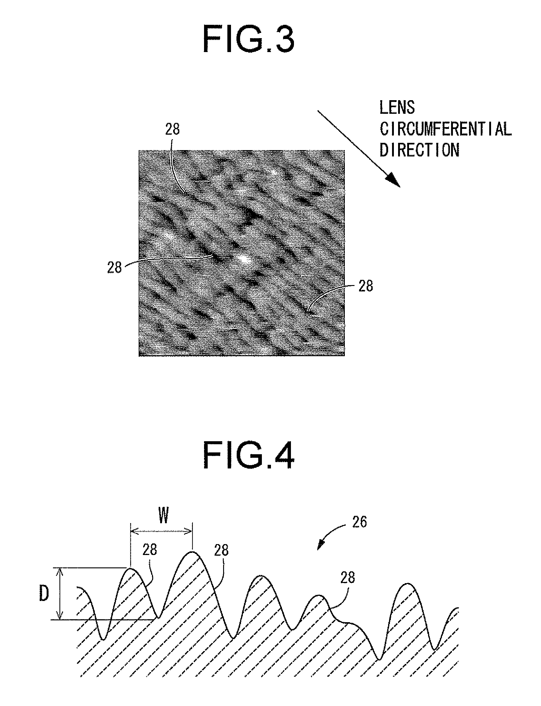
Plates corresponding to the intraocular lens according to the present invention, endowed with periodic patterns according to the manufacturing method of the present invention (periodic machined plates) and plates corresponding to intraocular lenses of conventional design lacking periodic patterns (non-periodic machined plates) were prepared and were subjected to comparative tests regarding the direction of cell growth in the respective plates.

To produce the periodic machined plates, a plate die of mechanical construction grade carbon steel material (S45C) was prepared, and a femtosecond laser shaped to a line by a cylindrical lens was directed onto the surface of ...


PUM

PropertyMeasurementUnit
lengthaaaaaaaaaa
lengthaaaaaaaaaa
lengthaaaaaaaaaa

Abstract

An intraocular lens adapted for deployment within a lens capsule. At least part of a lens surface of the intraocular lens constitutes a cell inducing region in which are directly formed a multitude of microgrooves. The microgrooves take a form of minute linear grooves and lands of depth dimension between 0.01 and 1.0 μm and width dimension between 0.1 and 2.0 μm extending with prescribed length in a circumferential direction on the lens surface. The minute linear grooves and lands are formed with a chained pattern connected in the circumferential direction of the lens surface and with a periodic pattern arrayed periodically in a diametrical direction so that the minute linear grooves and lands are formed without intervening spaces throughout the entire cell inducing region and impart visible light transmittance of 60% or above to the cell inducing region.

Description

TECHNICAL FIELDThe present invention relates to an intraocular lens adapted for use while accommodated within the lens capsule, and relates in particular to an intraocular lens that is effective in inhibiting secondary cataracts.BACKGROUND ARTIntraocular lenses intended to replace the crystalline lens have been used for some time to treat patients suffering from ocular disorders such as cataracts. In a typical procedure, after extracting and removing the crystalline lens from inside the capsule through a surgical incision made in the ocular tissue, such as the cornea (sclera) or anterior capsule portion of the lens, an insertion instrument or the like is used to insert the intraocular lens into the capsule through the surgical incision while folded back onto itself. Once inserted into the capsule, the intraocular lens is deployed inside the capsule to allow it to be used with the optical part thereof, which replaces the functionality of the crystalline lens, securely positioned with...

Claims


Application Information

Patent Timeline
Patent Type & Authority Applications(United States)
IPC IPC(8): A61F2/16B29D11/00
CPCA61F2/1613A61F2002/009B29L2011/0016B29D11/00326B29D11/023B29C33/40A61F2/16B29D11/00B29D16/00B29C71/04A61F2002/1681
Inventor KOBAYASHI, ATSUSHIYAMADA, KATSUNORISUZUKI, HIROAKI
Owner KOWA CO LTD
Why Eureka
Try Eureka