Substrate process apparatus, substrate process method, and computer readable storage medium

a technology of substrate and process equipment, applied in mechanical equipment, transportation and packaging, coatings, etc., can solve the problems of adversely affecting the uniformity of the process, the inability to monitor the change of pressure gauge, and the difficulty of directly measuring the flow rate of gases flowing through the corresponding evacuation lin

Active Publication Date: 2011-05-05
TOKYO ELECTRON LTD
View PDF141 Cites 369 Cited by
  • Summary
  • Abstract
  • Description
  • Claims
  • Application Information

AI Technical Summary

Benefits of technology

[0020]The data in the storage portion are obtained before the process is performed with respect to the substrate, by the steps of (a) closing the first pressure adjustment valve and opening the second pressure adjustment valve, (b) supplying a flow rate control gas to the vacuum chamber, adjusting the adjustment value of the conductance adjustment por...

Problems solved by technology

Incidentally, when the reaction gases are evacuated through the plural evacuation lines from the vacuum chamber, it is very difficult to directly measure flow rates of gases flowing through the corresponding evacuation lines, partly because an appropriate instrument capable of measuring the flow rates is not available.
In addition, when deposits gradually grow on an inner surface of one of the evacuation lines, the flow rate of gas to be evacuated through the evacua...

Method used


Image

  • Substrate process apparatus, substrate process method, and computer readable storage medium
  • Substrate process apparatus, substrate process method, and computer readable storage medium
  • Substrate process apparatus, substrate process method, and computer readable storage medium

Examples


first embodiment

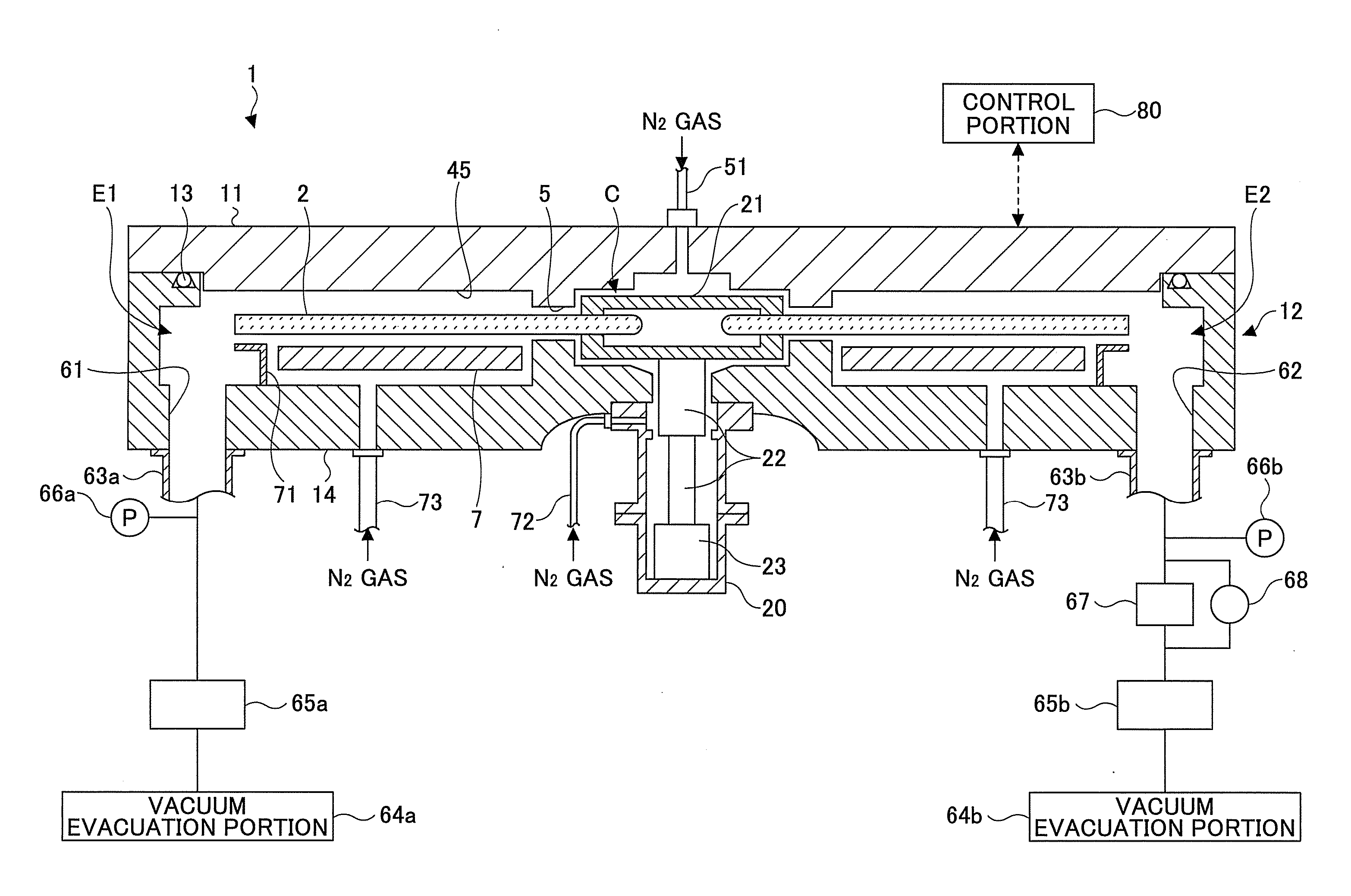
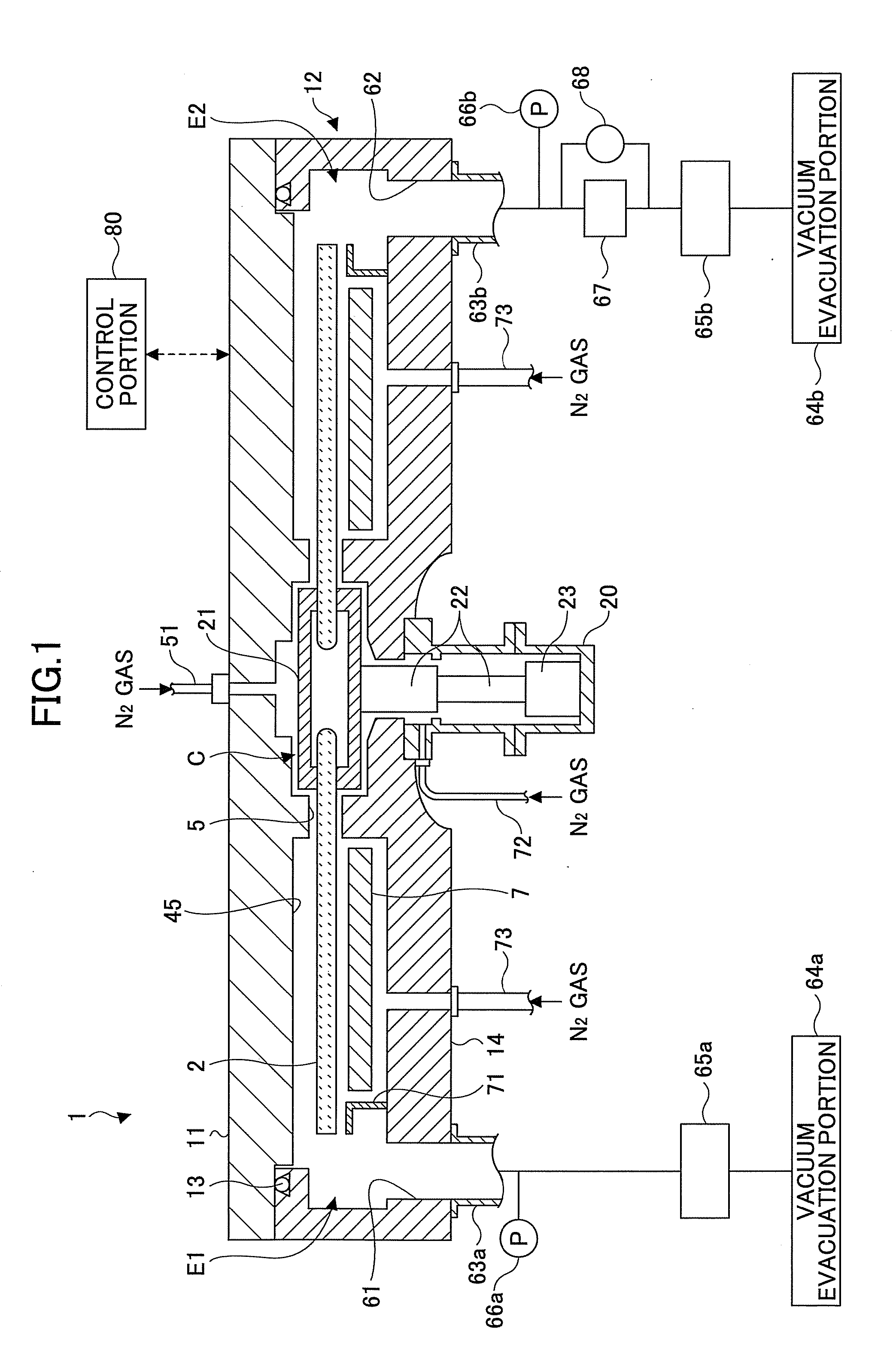
[0047]As shown in FIG. 1 (a cross-sectional view taken along I-I′ line in FIG. 3), a film deposition apparatus according to a first embodiment has a vacuum chamber 1 substantially having a top-view shape of a circle, and a turntable 2 that is located inside the chamber 1 and has a rotation center at a center of the vacuum chamber 1. The vacuum chamber 1 is made so that a ceiling plate 11 can be separated from a chamber body 12. The ceiling plate 11 is pressed onto the chamber body 12 via a sealing member such as an O ring 13 so that the vacuum chamber 1 is hermetically sealed, when the vacuum chamber 1 is evacuated to reduced pressures. On the other hand, the ceiling plate 11 can be raised by a driving mechanism (not shown) when the ceiling plate 11 has to be removed from the chamber body 12.

[0048]The turntable 2 is fixed onto a cylindrically shaped core portion 21. The core portion 21 is fixed on a top end of a rotational shaft 22 that extends in a vertical direction. The rotationa...

second embodiment

[0101]Although the film deposition apparatus having two evacuation passages 63a, 63b has been explained in the first embodiment, a film deposition apparatus according to other embodiments may have three evacuation passages. Such a film deposition apparatus is explained as a second embodiment, with reference to FIGS. 15 and 6. Incidentally, the same reference symbols are given to the components or members explained in the first embodiment, and repetitive explanations are omitted.

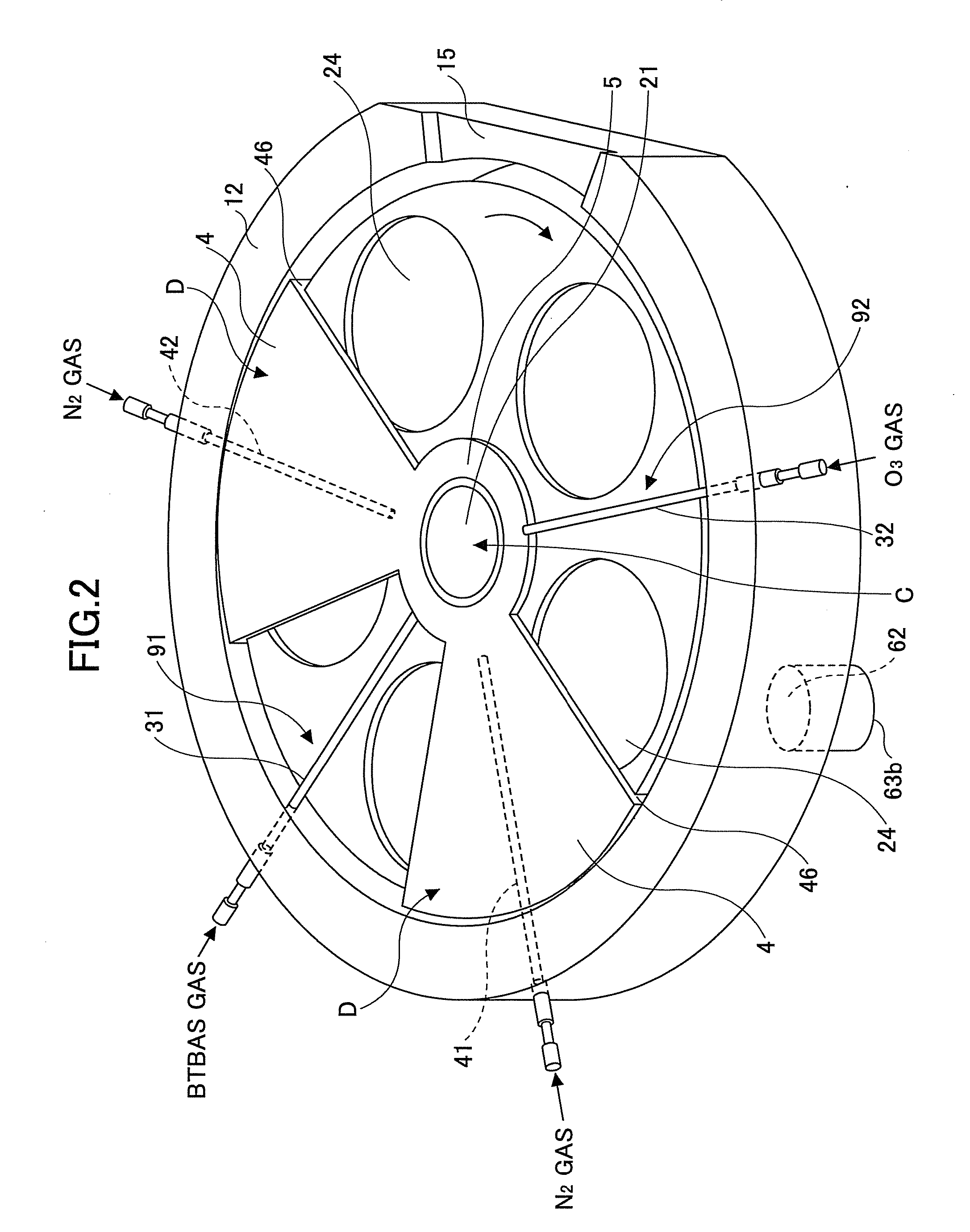
[0102]In the film deposition apparatus according to the second embodiment, there are provided three reaction gas nozzles 31, 32, 33. A separation area D is arranged between the first process area 91 where a first reaction gas is supplied from the reaction gas nozzle 31 and the second process area 92 where a second reaction gas is supplied from the second reaction gas nozzle 32, and is provided with the separation gas nozzle 41. In addition, another separation area D is arranged between the first process area ...

third embodiment

[0119]While the film deposition apparatus according to embodiments of the present invention has been described, where plural reaction gases that are reacted with one another are supplied to the vacuum chamber 1, thereby depositing a film on the wafers W, the present invention may be applied to an etching apparatus, where a process gas (etching gas) is supplied to a vacuum chamber, thereby performing an etching process. Such an etching apparatus is explained as a third embodiment, with reference to FIGS. 21 and 22.

[0120]In FIG. 21, a reference symbol 201 indicates a vacuum chamber and a reference symbol 202 indicates a susceptor on which a substrate S such as a square glass substrate for a Liquid Crystal Display (LCD) or a Flat Panel Display (FPD) having a side length of about several meters is placed. The susceptor 202 serves as a lower electrode. In an upper area of the vacuum chamber 201, a shower head 203 serving as a process gas supplying portion is provided. A halogen series el...


PUM

PropertyMeasurementUnit
Pressureaaaaaaaaaa
Electrical conductanceaaaaaaaaaa

Abstract

A vacuum chamber is evacuated through a first evacuation passage provided with a first valve and a second evacuation passage provided with a second valve. An opening degree of the first valve is adjusted so that a pressure in the vacuum chamber becomes substantially equal to a process pressure P; an opening degree of a butterfly valve further provided in the second evacuation passage is adjusted to substantially equal to a set value determined by a table in order to set flow rates of gases to be evacuated through the first evacuation passage and the second evacuation passage to be substantially equal to corresponding set values determined by the recipe; and an opening degree of the second valve is adjusted so that a measurement value of a differential pressure gauge further provided in the second evacuation passage becomes substantially equal to a differential pressure written in the table.

Description

CROSS-REFERENCE TO RELATED APPLICATION[0001]This application claims the benefit of priority of Japanese Patent Application No. 2009-253321 filed on Nov. 4, 2009, with the Japanese Patent Office, the entire contents of which are hereby incorporated by reference.BACKGROUND OF THE INVENTION[0002]1. Field of the Invention[0003]The present invention relates to a substrate process apparatus and substrate process method that process a substrate under vacuum using a process gas, and a storage medium that stores a computer program that causes the substrate process apparatus to perform the substrate process method.[0004]2. Description of the Related Art[0005]In a semiconductor device fabrication process, when vacuum processes such as film deposition, etching, or the like are performed with respect to substrates such as a semiconductor wafer (referred to as a wafer, hereinafter) in a vacuum chamber, the vacuum chamber is evacuated to reduced pressures through plural evacuation lines. In such a...

Claims


Application Information

Patent Timeline
IPC IPC(8): F17D1/00
CPCC23C16/45502C23C16/45551C23C16/45557H01L21/68771H01L21/67253H01L21/68764C23C16/45587Y10T137/8376
Inventor ORITO, KOHICHIHONMA, MANABUTAMURA, TATSUYA
Owner TOKYO ELECTRON LTD
Why Eureka
Try Eureka