Bumper energy absorber and method of fabricaitng and assembling the same

a technology for bumpers and energy absorbers, which is applied in the direction of bumpers, shock absorbers, elastic dampers, etc., can solve the problems of not being specifically designed for energy absorbers, current bumper systems require expensive molds, and the cost of these molds

Inactive Publication Date: 2011-05-05
BATOR MARY ANN
View PDF36 Cites 29 Cited by
  • Summary
  • Abstract
  • Description
  • Claims
  • Application Information

AI Technical Summary

Problems solved by technology

However, many of the current bumper systems require expensive molds to manufacture the commonly used injection molded bumper beam energy absorbers.
Due to the high cost of these molds, energy absorbers are not specifically designed for each specific type of vehicle.
Instead, a one-size-fits-all-type energy absorber is used on many different vehicles, often adding excess weight to the vehicle and excess cost due to the use of unnecessary materials.

Method used


Image

  • Bumper energy absorber and method of fabricaitng and assembling the same
  • Bumper energy absorber and method of fabricaitng and assembling the same
  • Bumper energy absorber and method of fabricaitng and assembling the same

Examples


Embodiment Construction

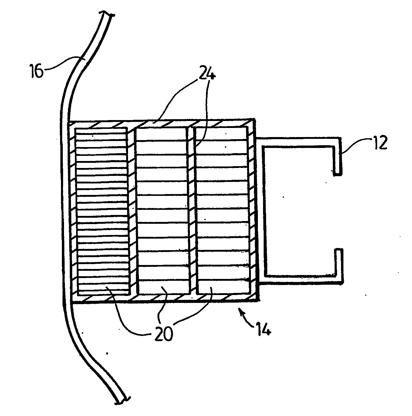
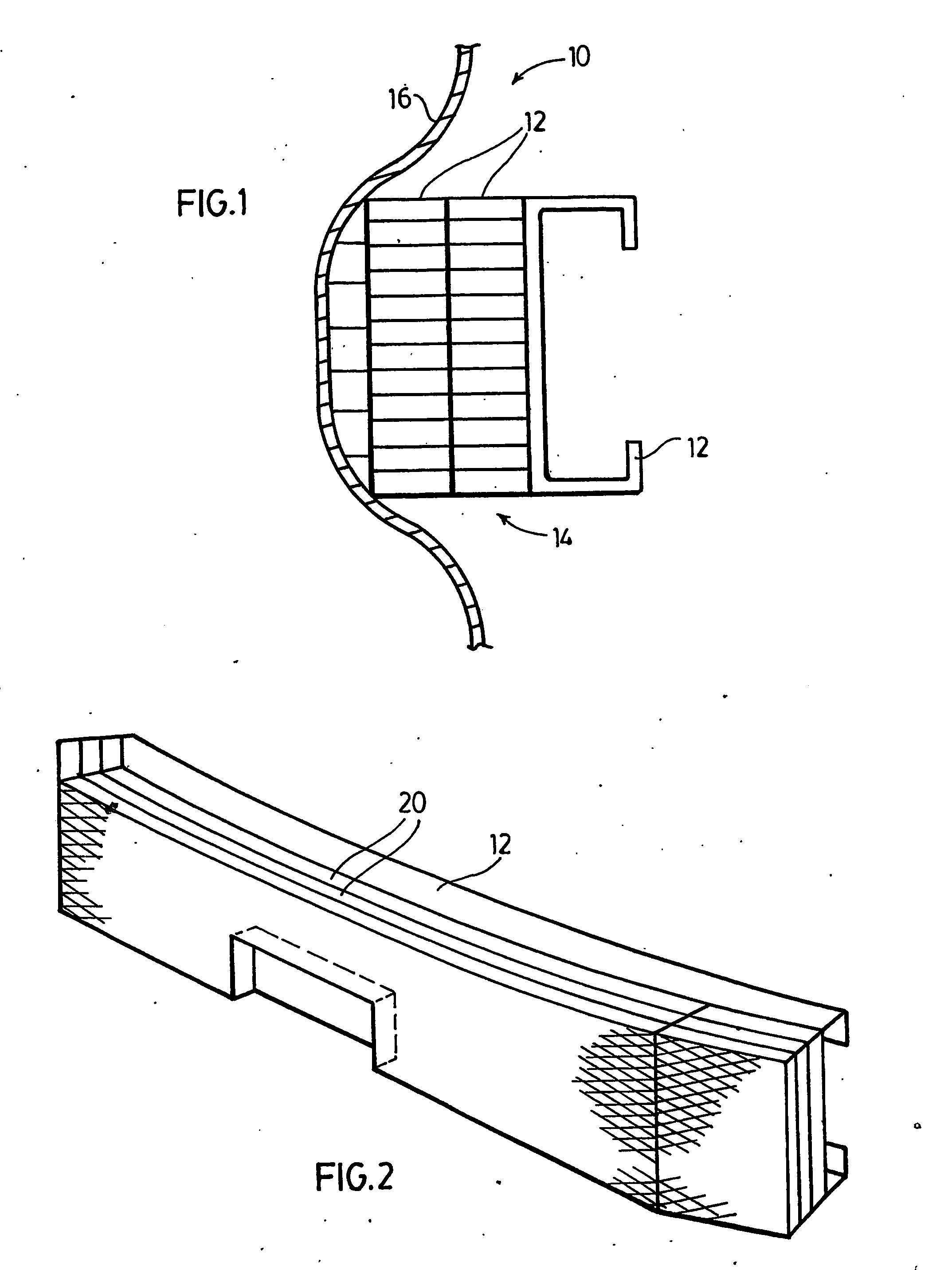
[0014]Referring to the Figures, an energy absorbing bumper system is generally indicated at 10. The energy absorbing bumper system 10 includes an impact beam 12, an energy absorber 14, and a fascia 16. The energy absorber 14 includes layers of extruded cell panels 20.

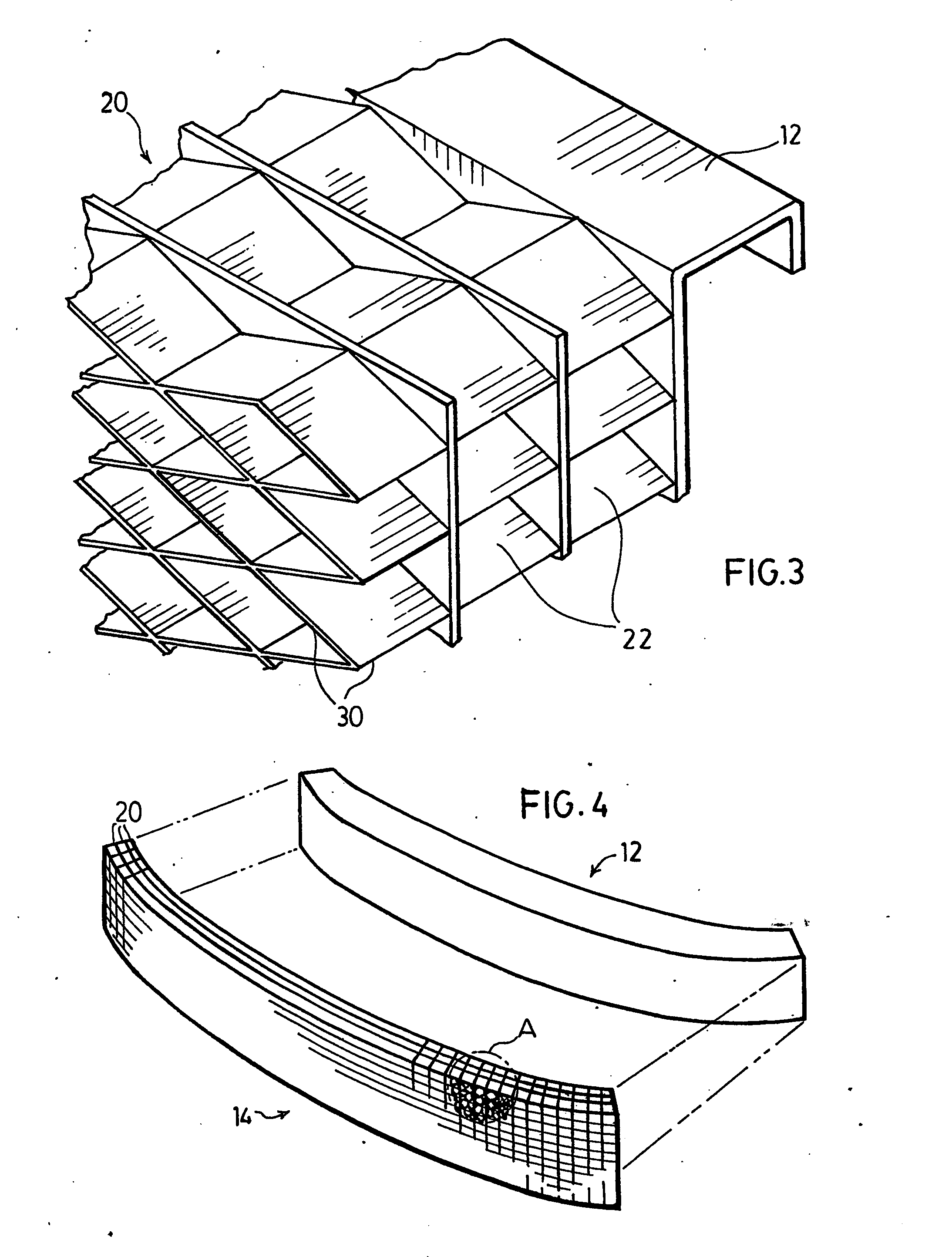
[0015]The cell panels 20 may be of any extrudable material, preferably a low-cost olefinic material. The extrusion process eliminates the need for expensive molds required to manufacture injection molded bumper beam energy absorbers in order to accommodate different vehicles. Additionally, the extruded part is lighter than foamed energy absorbers and capable of absorbing more energy. Each cell panel 20 is made up from a plurality of joined hollow cells 22 and 22′ formed during the extrusion process, which results in an open-cell network. The cells 22, 22′ can be of any shape such as honeycomb, diamond or oval in shape, as shown in FIGS. 3 and 4 and may have any geometric cross-sectional shapes. The extrusion process can...


PUM

PropertyMeasurementUnit
energyaaaaaaaaaa
absorb energyaaaaaaaaaa
sizeaaaaaaaaaa

Abstract

A bumper beam energy absorbing system (10) is disclosed for absorbing impact energy exerted on an automotive vehicle. The energy absorbing system (10) includes a rigid, structural impact beam (12), a decorative fascia (16), and an energy absorber (14) sandwiched between the impact beam (12) and fascia (16). The impact beam (12) is adapted to attach the energy absorber to the vehicle while the fascia (16) decoratively covers and conceals the energy absorber (14). The energy absorber (14) is comprised of layers of cell panels (20). Each cell panel (20) is extruded into an open cell network in which interconnected closed loop cell walls define a plurality of open cells, thereby creating the network. The cross-section of the cells (22, 22′) in one cell panel may differ to adjust the amount of energy absorbed by a particular section of the panel. Likewise, the overall open cell network may vary between the layers, thereby adjusting the amount of energy absorbed by each particular layer.

Description

FIELD OF THE INVENTION[0001]This invention relates to a motor vehicle bumper assembly. More particularly, this invention relates to a motor vehicle bumper beam energy absorber that is constructed of extruded plastic in a cell network, and a method of fabricating and assembling the same.DESCRIPTION OF THE PRIOR ART[0002]Bumpers are used on automobiles for absorbing shock and impact from collisions, thereby preventing and / or decreasing injury to persons and damage to property, including the vehicle. Automobile bumpers typically include an impact or reinforcement beam, energy absorbers surrounding the beam, and a fascia surrounding the energy absorber. The beam, usually constructed of high strength steel or aluminum, is attached to the vehicle frame. The energy absorber is typically a foam material although hydraulic or gas piston and cylinder assemblies have been used. The third main component, the fascia, is the visible exterior of the bumper assembly, and is typically made of plasti...

Claims


Application Information

Patent Timeline
Patent Type & Authority Applications(United States)
IPC IPC(8): B60R19/26B23P11/00B60R19/18B60R21/34F16F7/12
CPCB60R19/18B60R2019/1866Y10T29/49826F16F7/121B60R2021/346
Inventor BATOR, MARY, ANN
Owner BATOR MARY ANN
Why Eureka
Try Eureka