Lightning detection
- Summary
- Abstract
- Description
- Claims
- Application Information
AI Technical Summary
Benefits of technology
Problems solved by technology
Method used
Image

Examples
Embodiment Construction
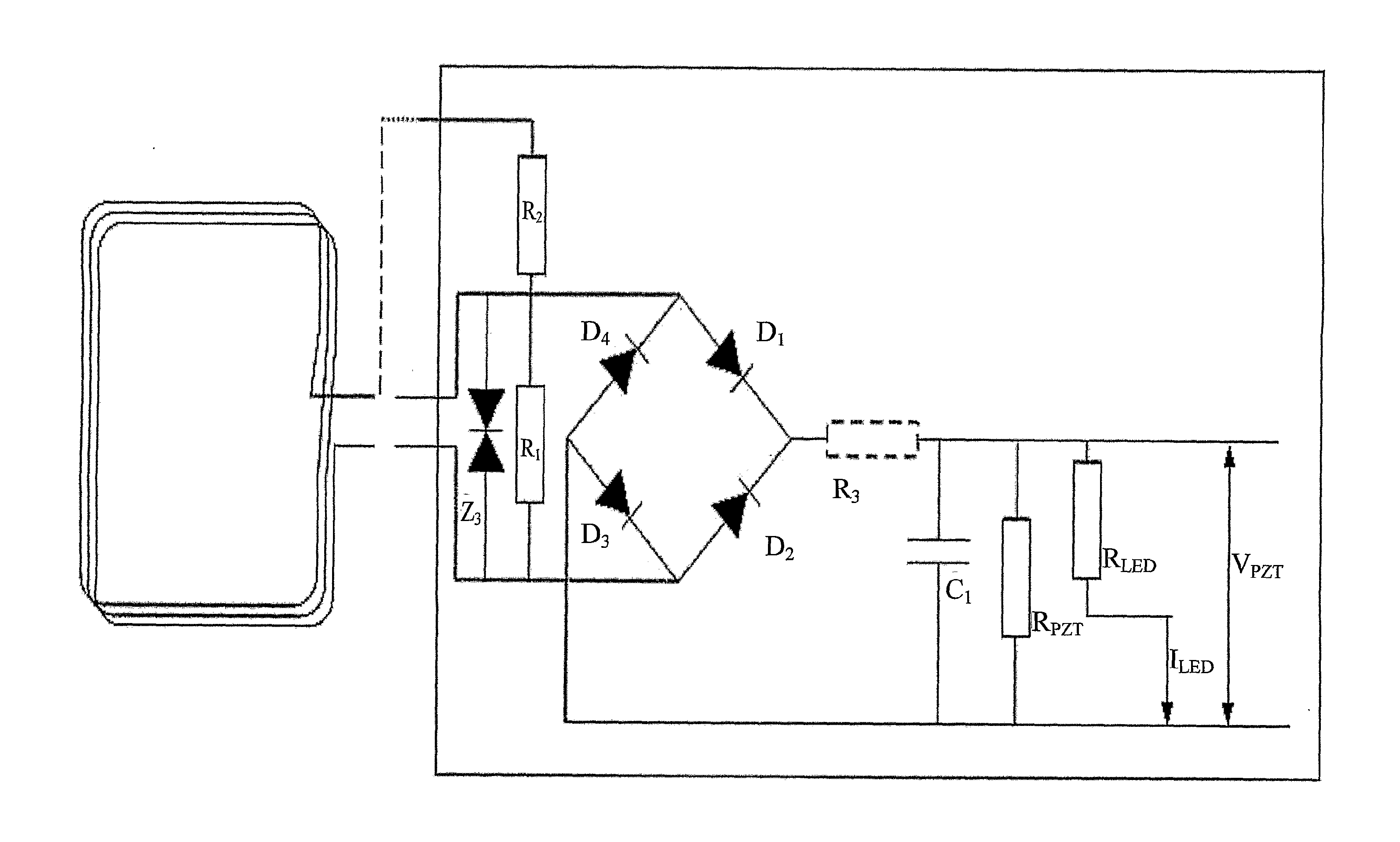
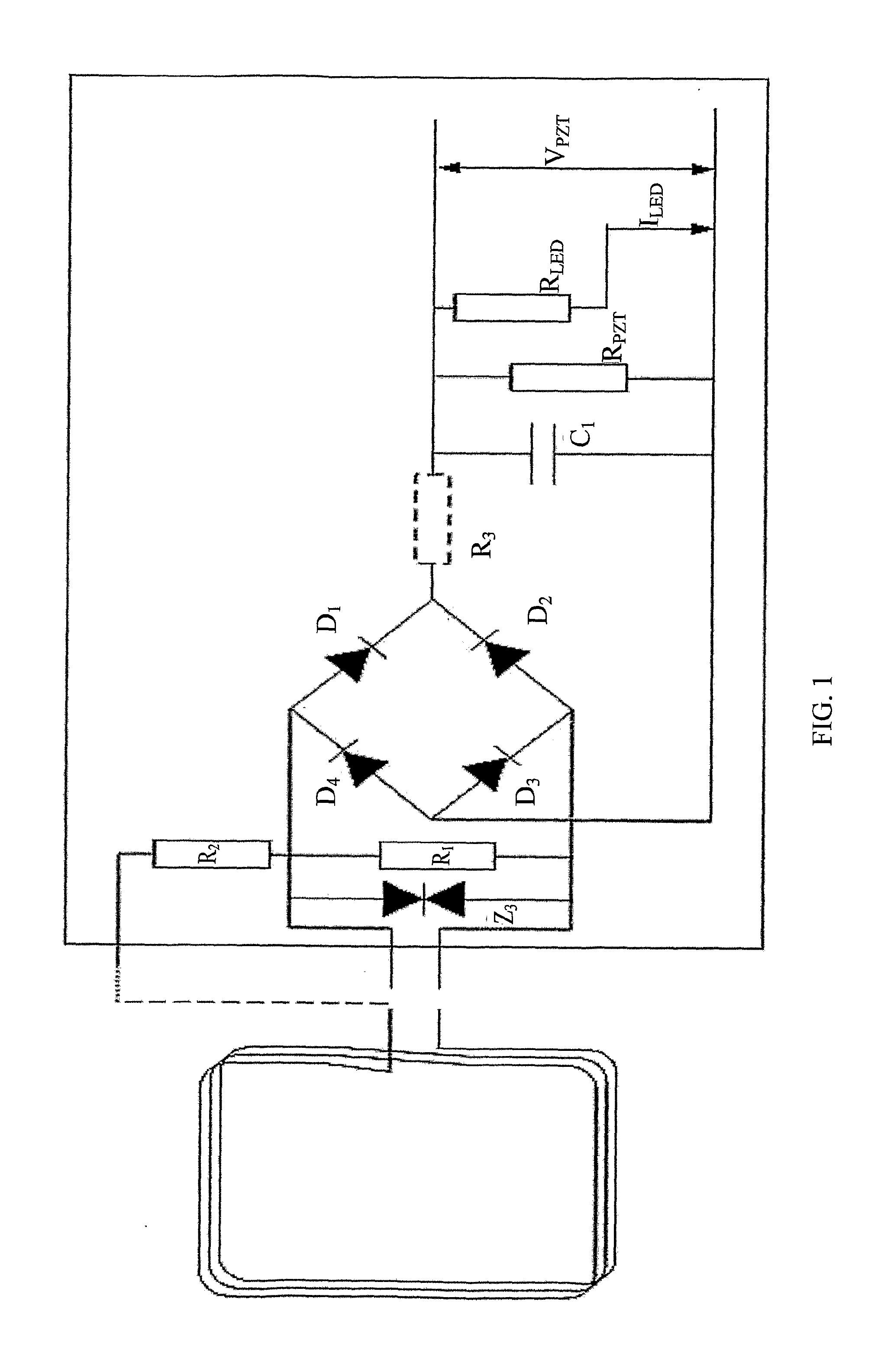
[0025]FIG. 1 is a schematic diagram of a lightning detector according to an embodiment of the invention. An inductive loop antenna 1 is arranged in the vicinity of a lightning conductor. The axis of the antenna 1 about which the turns of the loop are wound is arranged substantially perpendicularly to the direction of current flow through the lightning conductor. In this way, the inductive coupling between the lightning conductor and the antenna is maximised.
[0026]The antenna 1 is arranged in parallel with one or more Zener diodes Z3 which protects the rest of the circuit from excessive current surges. A first resistor R1 is arranged in parallel with the antenna 1 to dissipate the induced current in the antenna. A second resistor R2 is provided in series with the first resistor R1 to form a potential divider in order to limit the voltage applied to the components of the device that are in parallel with the first resistor R1. A full wave rectifier D1-D4 is provided across the first re...
PUM
 Abstract
Description
Claims
Application Information
 - Generate Ideas
- Intellectual Property
- Life Sciences
- Materials
- Tech Scout
- Unparalleled Data Quality
- Higher Quality Content
- 60% Fewer Hallucinations
Browse by: Latest US Patents, China's latest patents, Technical Efficacy Thesaurus, Application Domain, Technology Topic, Popular Technical Reports.
© 2025 PatSnap. All rights reserved.Legal|Privacy policy|Modern Slavery Act Transparency Statement|Sitemap|About US| Contact US: help@patsnap.com