
Device for Supporting Light Emitting Module

a technology of light-emitting modules and supporting devices, which is applied in the direction of lighting support devices, lighting and heating apparatus, light source combinations, etc., can solve the problems of complex and excessively large structure, difficult design modification, and no supporting device that can be easily installed, etc., to achieve simple configuration and easy installation.

Inactive Publication Date: 2011-05-05
OPTOWORLD
View PDF4 Cites 50 Cited by
  • Summary
  • Abstract
  • Description
  • Claims
  • Application Information

AI Technical Summary

Benefits of technology

[0035]Preferably, as the present invention according to Claim 14, the mounting component may also be in a butterfly nut shape formed inside the edge end portion hanging out sideways of the T bar in a dimension and a shape that can be fixed inside the edge end portion by inserting from an opening in a slit shape on a bottom side of the T bar and making a half turn. According to the present invention of Claim 14, the fixation of the supporting device with a screw on the edge end portion of a T bar on a system ceiling can be made easier further only to make a half turn.
[0036]According to the device for supporting a light emitting module of the present invention, it has a large recess groove portion having a length in a dimension larger than the dimensions of a long side of the light emitting module and the large recess groove portion has left and right interior walls provided with a small recess groove portion into which a long side of the light emitting module is fitted and also provided with a threaded hole to enable fastening with a screw. This enables a device for supporting a light emitting module to be easily installed on an arbitrarily ceiling with a simple configuration and with a light emitting module for lighting. In addition, since the number of light emitting modules on board can be modified only by modifying the dimension in length in the long side direction of the supporting device, a supporting device can be easily manufactured that corresponds to the number of light emitting modules to be used by, for example, cutting a supporting device having a length of several fold or more of the light emitting modules in accordance with the required number or the like.

Problems solved by technology

However, conventionally, there was no supporting device that can easily install standardized light emitting modules for lighting of light emitting diodes on a ceiling formed by fixing ceiling plates on a ceiling foundation with the number of light emitting modules being arbitrarily variable.
Therefore, conventionally, it had to use an expensive lighting device for exclusive use having outer dimensions formed by matching in dimensions to enable housing of the light emitting modules, build a supporting device for oneself that is expensive and requires many steps, or modify a mounting device for fluorescent lights for general use into one for light emitting diodes with processing steps and fix it on a ceiling joist or the like with a supporting device for exclusive use.
Such conventional devices for supporting light emitting modules are often converted from those for fluorescent lights in general, and therefore they used to have a complex and excessively large structure and excessive strength as those for light emitting modules by having an area surrounding the light emitting portion, other than the outgoing plane, covered with a large thick wood board or the like in order to allow a stabilizer including a transformer unit, such as an inverter, to be placed thereon and protect fluorescent lights damaged easily.
Therefore, design modification is also not easy, and the lighting rows of the light emitting modules cannot be easily modified.

Method used


Image

  • Device for Supporting Light Emitting Module
  • Device for Supporting Light Emitting Module
  • Device for Supporting Light Emitting Module

Examples


first embodiment

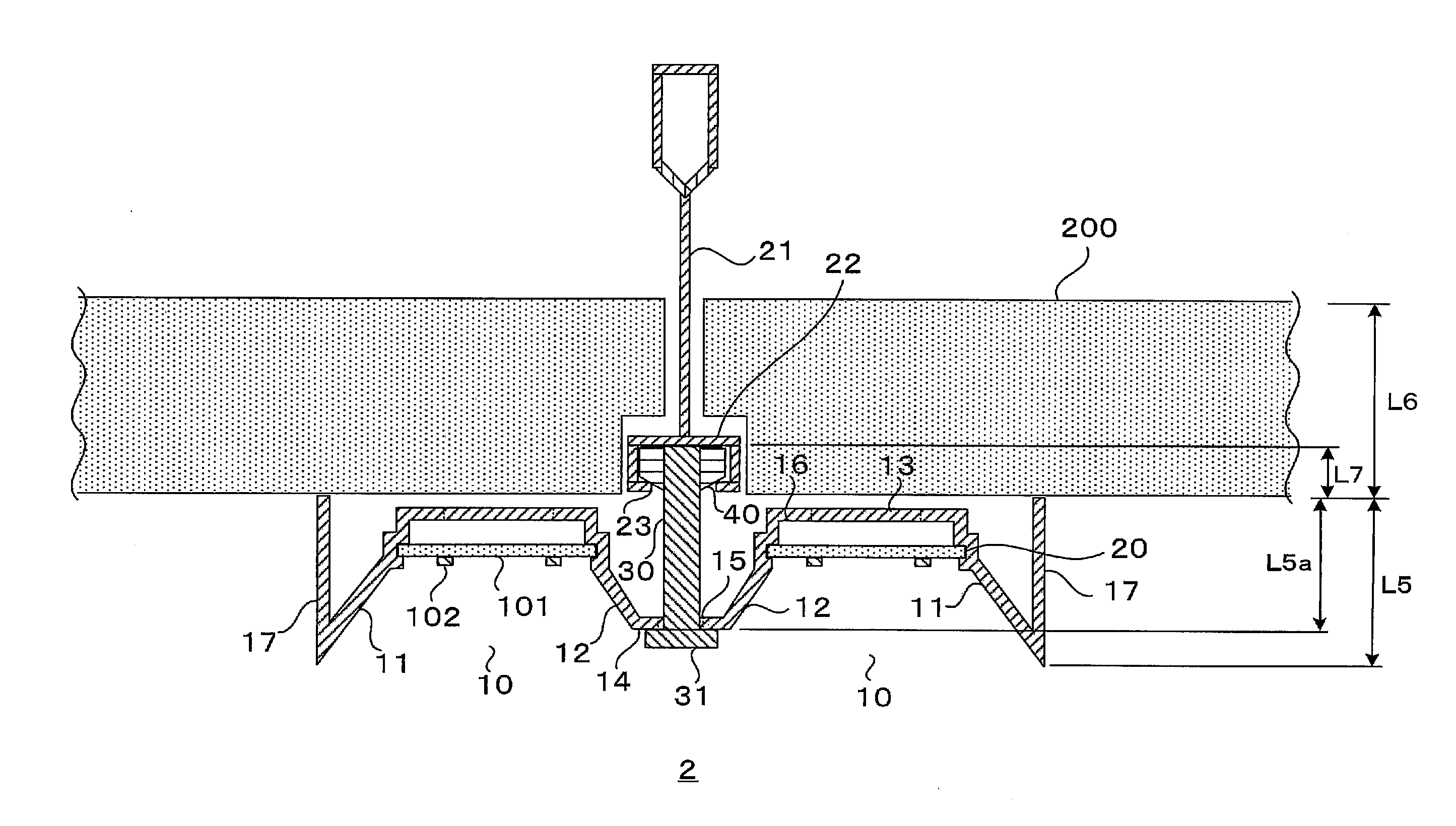
[0056]FIG. 3 is a cross sectional view illustrating an outline configuration in a case that the supporting device of the first embodiment of the present invention is installed on the bottom side of a T bar on a system ceiling together with the light emitting modules.

[0057]T bars 21 are suspended from a roof, an upstairs floor, or the like, are installed vertically and horizontally in parallel in predetermined dimensions, such as 600 mm or 640 mm, and are frame components to form a ceiling by dropping the ceiling plates 200 in standardized dimensions, such as 600 mm×600 mm. An edge end portion 22 is a part at an edge end hanging out sideways of the T bar 21. The system ceiling is in predetermined dimensions, such as 600 mm or 640 mm, as mentioned above, and a grid in which the T bars 21 in parallel are arranged vertically and horizontally in a lattice pattern is formed. Accordingly, the intervals between the T bars 21 in parallel are also in a predetermined dimension, such as 600 mm ...

second embodiment

[0064]FIG. 4 is a cross sectional view illustrating an outline configuration in a case of installing a supporting device of the second embodiment of the present invention in a ceiling joist (M bar) of a light-gauge steel foundation together with light emitting modules. An M bar 50 of a light-gauge steel foundation is a square material having a cross section of an approximate square shape and having an opening on the top side, and is fixed on a ceiling joist receiver 61 with a clip 60. The M bar 50 and the clip 60 are available in a single size (25 mm in width) and a double size (50 mm in width), and a supporting device 3 of the present embodiment is possible to install in either size.

[0065]The supporting device 3 is configured with, in addition to the supporting device basic unit 1 illustrated in FIG. 2, in order to install the light emitting modules 100 on a ceiling of a light-gauge steel foundation (light ceiling), a screw 32 in which the length dimension of the screw 30 of the fi...

third embodiment

[0070]FIG. 5 is a cross sectional view illustrating an outline configuration in a case that a supporting device of the third embodiment of the present invention is installed in the ceiling plate 200 together with the light emitting modules.

[0071]A device supporting 4 is configured with, in addition to the supporting device basic unit 1 illustrated in FIG. 2, in order to install the light emitting modules 100 on the ceiling plate 200 having an arbitrary thickness dimension, a screw 33 in which the length dimension of the screw 30 of the first embodiment, for example, is extended to a roof side of the ceiling plate 200 so as to enable fixation on the ceiling plate 200. A mounting component 70 has a fixing portion 72 screwed together with the screw 33 in FIG. 5 and formed and arranged to enable to press a non-indoor side (roof side) of the ceiling plate 200, and is provided with a threaded hole 71 screwed together with the screw 33.

[0072]In the mounting component 70, the thickness dime...


PUM


Abstract

Provided is a supporting device that enables light emitting modules to be easily installed on a ceiling for lighting and is easy to modify the light emitting modules with a simple configuration. For that purpose, a supporting device of the present invention has a large recess groove portion having a width dimension smaller than a dimension of a short side of the light emitting modules and having a length dimension larger than a dimension of a long side of the light emitting modules and a screw fixation portion provided with a threaded hole for fastening on the ceiling. On left and right interior walls of the large recess groove portion, small recess groove portions, parallel to the large recess groove portion, having a cross sectional shape approximately equal to a cross sectional shape of a peripheral end portion of the long side of the light emitting modules are formed in an arrangement facing on the left and right respectively. An interval dimension between facing groove back side portions of the respective small recess groove portion is approximately identical to a dimension of the short side of the light emitting modules.

Description

TECHNICAL FIELD[0001]The present invention relates to a supporting device in a case of installing a light emitting module having a light emitting element, such as a light emitting diode, arranged on a substrate as a lighting device on a ceiling surface.BACKGROUND ART[0002]On a ceiling inside a normal wooden house, a wooden ceiling foundation is formed that is hung with a ceiling hanger from a roofing material, a ceiling hanger receiver, or the like, and a ceiling plate (ceiling board) in a flat plate shape is configured to be fixed thereto with nails, fastening screws, or the like. Materials for the ceiling plate include those based on wood (sawn general lumbers / precious wood, plywood, laminated lumbers, fibrous wood), based on plaster, based on cement (cement boards / rock wool boards), based on plastic, based on metal, based on ceramics / stone, or the like. Such a ceiling foundation is made by, for example, forming ceiling joist receivers, which are wooden square logs having a cross...

Claims


Application Information

Patent Timeline
IPC IPC(8): F21S8/00
CPCF21S8/04F21V21/02F21Y2101/02F21S8/026E04B9/241F21Y2113/00F21V21/04E04B9/183F21V21/049F21Y2115/10
Inventor AGO, KAZUFUSATSUJI, KATSUNARI
Owner OPTOWORLD
Learn More