Tuner device

a technology of a tuning device and a clock portion, which is applied in the direction of measuring devices, speech analysis, instruments, etc., can solve the problems of k clock portion, measurement error with respect to the duration of one cycle of the measured signal, and the response time at values that are not properly maintained, and achieve the effect of reducing the number of errors and reducing the accuracy of the measured signal

Inactive Publication Date: 2011-05-05
ROLAND CORP
View PDF2 Cites 3 Cited by
  • Summary
  • Abstract
  • Description
  • Claims
  • Application Information

AI Technical Summary

Benefits of technology

[0027]As such, the smallest measurement time is the time that realizes the required pitch error accuracy. Accordingly, until it becomes a time at or above this smallest measurement time, the time of each cycle of a signal is continuously and discretely measured for each 1 cycle, and the error accuracy of the pitch of the signal, which is calculated from the cumulative time and the counted frequencies, satisfies the required error accuracy. The cumulative cycle measurement means operates so that, when the pitch of the signal is high, the duration of one cycle of a signal is short and increases the number of times of cumulative addition. As such, the cumulative time becomes the smallest measurement time or more. On the other hand, when the pitch of the signal is low, the duration of one cycle of the signal is long and reduces the number of times of cumulative addition. As such, the cumulative time becomes the smallest measurement time or more. Accordingly, the cumulative cycle measurement means causes the number of times of cumulative addition to change in response to the pitch of the measured signal and operates so that the cumulative time becomes the smallest measurement time or more. Here, the smallest measurement time, as mentioned, is the time that realizes the required pitch error accuracy. Consequently, the pitch of the signal calculated by the above-described method that uses the cumulative time satisfies the required error accuracy.
[0029]Because the frequency of the clock signal can be lowered upon both the pitch error accuracy of the measured signal and the response time having satisfied the values required as the design conditions (after having maintained values with which there is no problem from a practical standpoint), current consumption can be reduced.
[0032]A pitch detection device may include (but is not limited to) an input means, a clock generation means, a pitch calculation means, a cycle detection means, a clock counting means, a cumulative clock counting means, and a frequency counting means. The input means may be for inputting a signal. The clock generation means may be for generating a clock signal. The pitch calculation means may be for calculating a pitch of the signal by determining a number of clocks in one cycle of the signal that regards one clock of the clock signal as the smallest base unit. The cycle detection means may be for detecting one cycle of a waveform of the signal. The clock counting means may be for counting the number of clocks of one cycle of the signal for each one cycle of the signal detected by the cycle detection means. The cumulative clock counting means may be for cumulatively adding, for every one cycle of the signal, the number of clocks corresponding to each one cycle of the signal counted by the clock counting means to obtain a cumulative number of clocks. The cumulative adding may end when the cumulative number of clocks equals or exceeds a smallest number of clocks that realizes a required pitch error accuracy. The frequency counting means may be for counting frequencies of the signal included within the cumulative number of clocks when the cumulative adding ends. The pitch calculation means may calculate the pitch of the signal from a frequency of the clock signal, the cumulative number of clocks, and a number of the counted frequencies of the signal. Such embodiments allow for some of the same benefits and uses as above.

Problems solved by technology

However, with such devices, when the frequency of the clock signal is lowered, the pitch error accuracy of the measured signal and the response time at values are not properly maintained.
First, when one cycle of the measure signal was the portion between the k−1 clock portion and the k clock portion, the measurement error with respect to the duration of one cycle of the measured signal, in the k clock portion, amounts to error due to the fact of being a little longer than the true duration of one cycle of the measured signal.
Second, when one cycle of the measured signal was the portion between the k clock portion and the k+1 clock portion, the measurement error with respect to the duration of one cycle of the measured signal, in the k clock portion, amounts to error due to the fact of being a little shorter than the true duration of one cycle of the measured signal.
As such, because the measurement of the duration of one cycle of the measured signal is discretely carried out with one clock of the clock signal as the smallest base unit, the errors that occur in that measurement also occur discretely.
However, this numerical formula results in reduced pitch error accuracy.
In other words, with the conventional pitch detection device, it is difficult to maintain both the pitch error accuracy d and the response time t to effective values simply by lowering the frequency Fc of a clock signal.

Method used


Image

  • Tuner device
  • Tuner device
  • Tuner device

Examples


Embodiment Construction

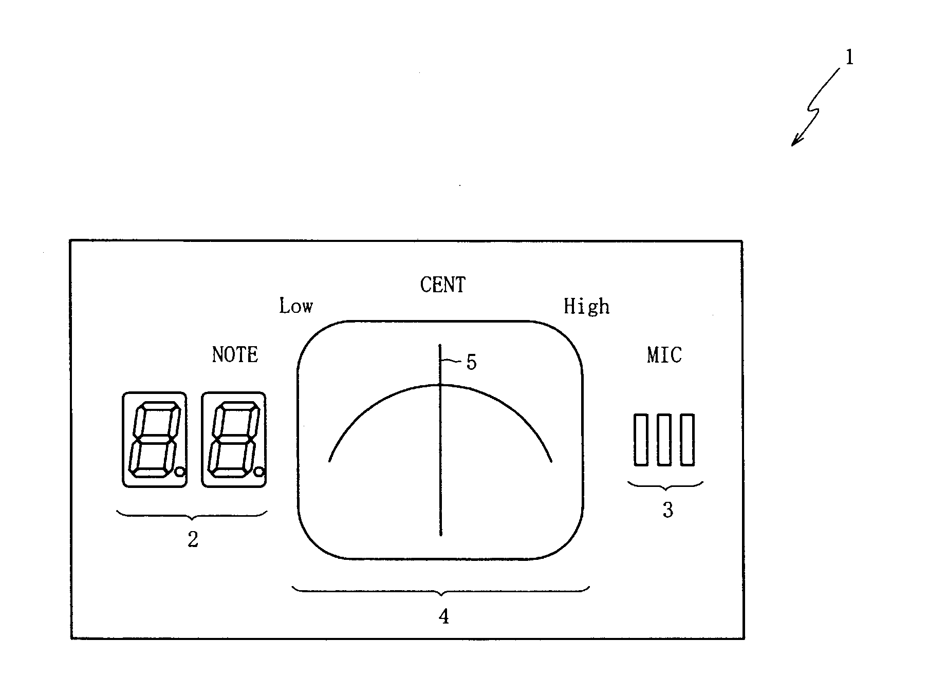
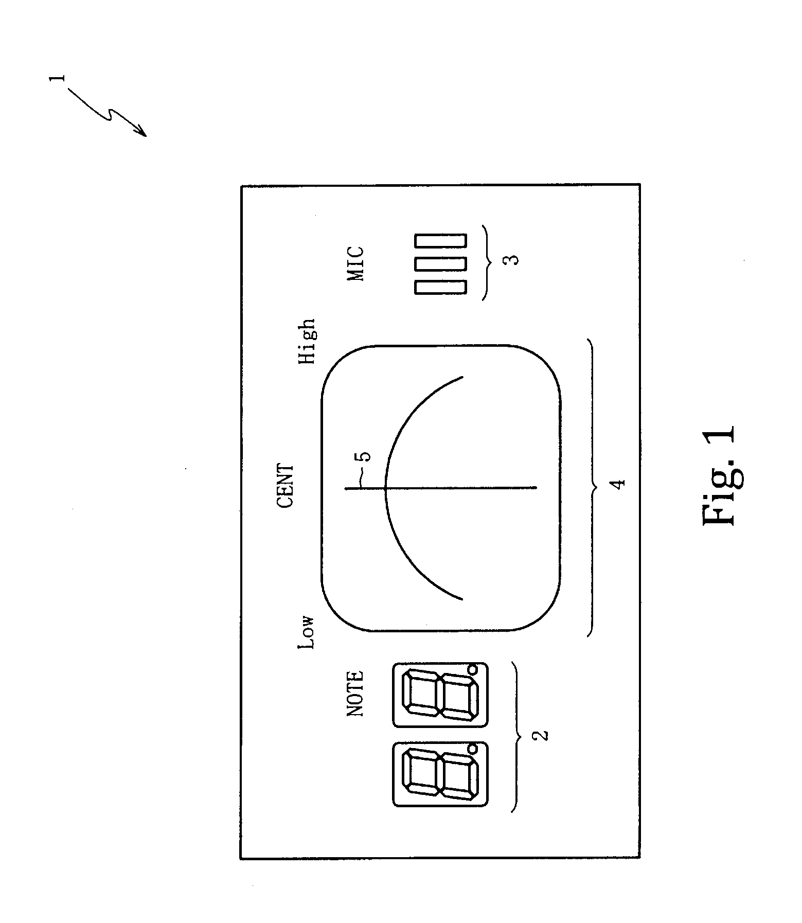
[0045]FIG. 1 is an exterior view of a tuner 1 for use with a musical instrument. In various embodiments, the tuner 1 may be configured to restrain current consumption (relative to conventional pitch detection devices in which the clock signal frequency is several hundred kHz) by lowering the clock signal frequency to about several tens of kHz after both the error accuracy (d) of a pitch of a musical note that has been input (so as to be measured) and the response time (t) have satisfied the values required as design conditions of the tuner 1.

[0046]The tuner 1 may use (but is not limited to) the design conditions provided below. The frequency (Fc) of a clock signal is 32.768 kHz; the detection range of the frequency (f) of a measured signal is 30.9 Hz-659 Hz; the required error accuracy (d) is ±1 cent; and the required response time (t) is within 150 ms. Other embodiments may employ different design conditions as may be required.

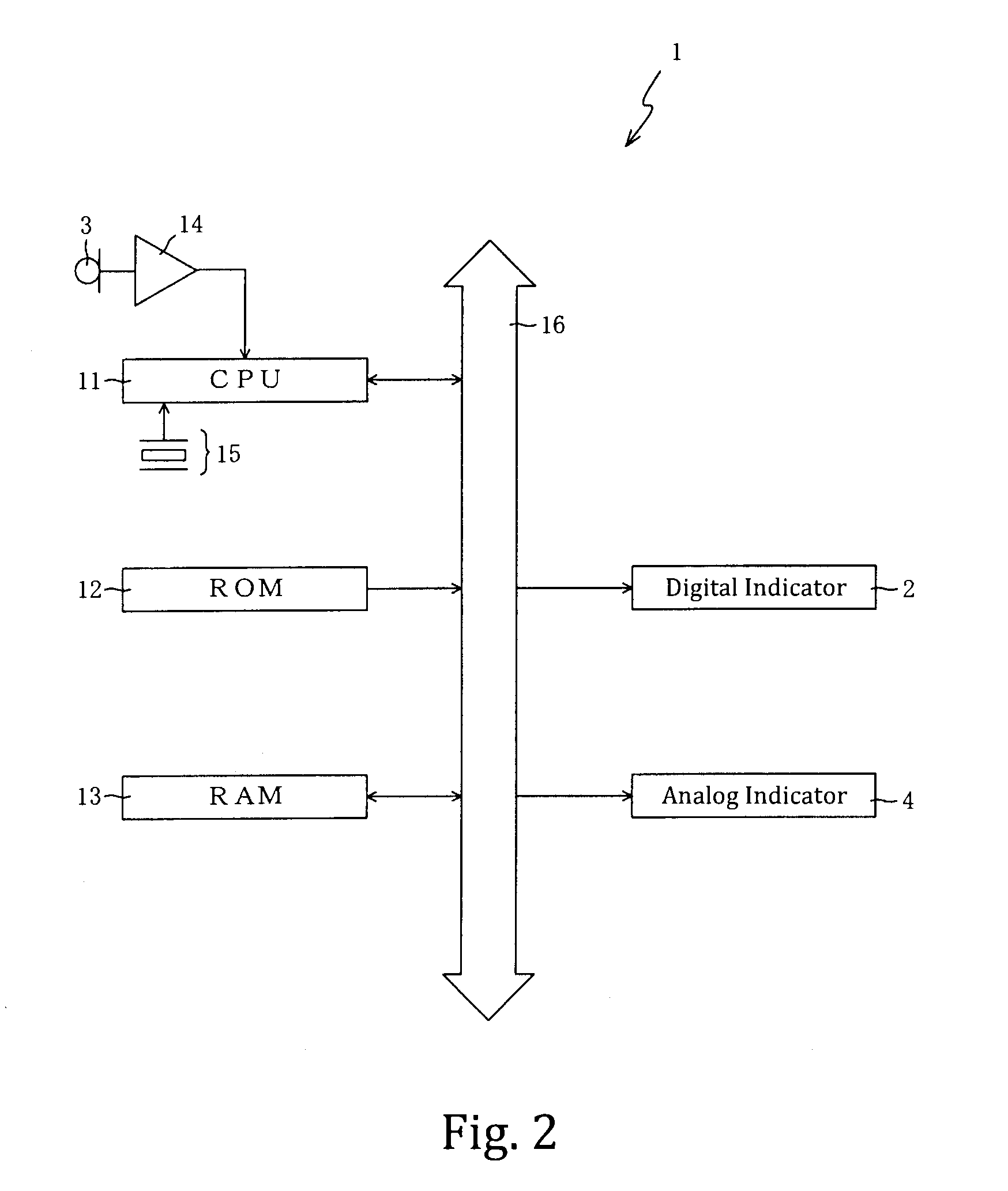
[0047]The tuner 1 may include, but is not limited to, a...


PUM


Abstract

A pitch detection device in which a frequency can be lowered after having maintained both a pitch error accuracy and a response time at practical values to reduce current consumption. Because a number of times of cumulative addition is changed in response to a pitch of a measured signal, a cumulative addition time sum equals or exceeds a constant T_SUM_MIN. Accordingly, a pitch error accuracy of the measured signal achieves a required error accuracy. Furthermore, a frequency of the clock signal is decided using a numerical formula (6) and a numerical formula (7) so that the constant T_SUM_MIN does not exceed a required response time. Accordingly, a response time is within the required response time regardless of whether the frequency of the measured signal is lowered.

Description

CROSS-REFERENCE TO RELATED PATENT APPLICATIONS[0001]Japan Priority Application 2009-251485, filed Oct. 30, 2009 including the specification, drawings, claims and abstract, is incorporated herein by reference in its entirety.BACKGROUND[0002]1. Field of the Invention[0003]Embodiments of the present invention generally relate to tuner device systems and methods, and, in specific embodiments, to tuner device systems and methods that allows for pitch detection that maintains pitch error accuracy and response time while allowing for the frequency of a clock signal to be reduced.[0004]2. Related Art[0005]In a conventional pitch detection device (e.g., a tuning device that detects the pitch of a musical note that has been input and indicates the deviation from a standard pitch), the pitch of the musical note that was input (pitch of the measured signal) is detected using a clock signal of several hundred KHz to several MHz. Here, the method of pitch detection of a measured signal in a conve...

Claims


Application Information

Patent Timeline
Patent Type & Authority Applications(United States)
IPC IPC(8): H04R29/00G10L25/90
CPCG01H3/06G10G7/02
Inventor NAKAYAMA, MASAYUKI
Owner ROLAND CORP
Why Eureka
Try Eureka