Device for osteosynthesis and for immobilization and stabilisation of tubular bones

a technology for applied in the field of devices for osteosynthesis and immobilization and stabilization of tubular bones, can solve the problems of patient breathing and mobility restrictions, exercise stability, and significant burden on patients, and achieve the effect of simple us

Active Publication Date: 2011-05-05
REISBERG ERHARD
View PDF5 Cites 18 Cited by
  • Summary
  • Abstract
  • Description
  • Claims
  • Application Information

AI Technical Summary

Benefits of technology

[0005]Proceeding from the known prior art, the object of the present invention is to provide a device for osteosynthesis, which is simple to use and is versatile.

Problems solved by technology

Nonetheless, the burden on the patient is significant.
For example, the patient's breathing and mobility may be restricted.
These methods, however, suffer in particular from the disadvantage that the desired exercise stability, i.e. a state in which the thorax can undergo slight loading, is usually not achieved immediately.

Method used


Image

  • Device for osteosynthesis and for immobilization and stabilisation of tubular bones
  • Device for osteosynthesis and for immobilization and stabilisation of tubular bones
  • Device for osteosynthesis and for immobilization and stabilisation of tubular bones

Examples


Embodiment Construction

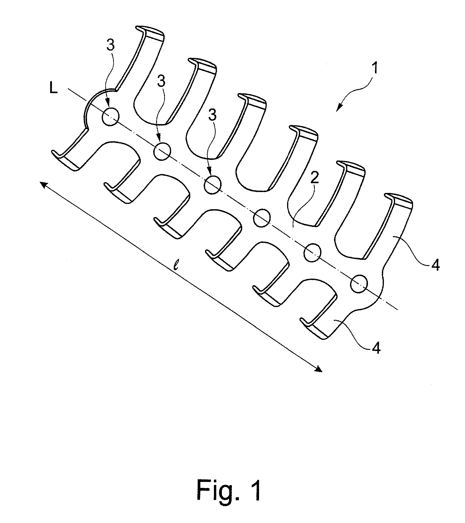
[0037]FIG. 1 shows an inventive implant 1. It has a central fillet 2 extending along a longitudinal axis L. The fillet 2 has a length 1, in which openings 3 are formed at regular intervals. At the level of the openings 3 and extending at right angles on both sides are clamps (pairs of clamps) 4, which, when the implant 1 is inserted, are brought into mutual engagement with a tubular bone and clamped to it.

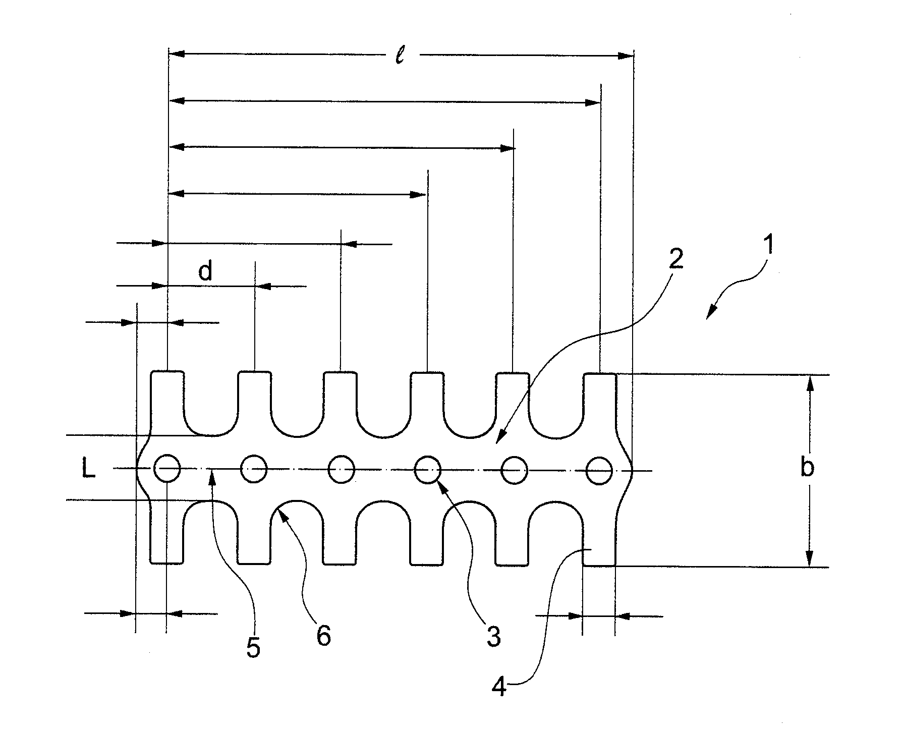
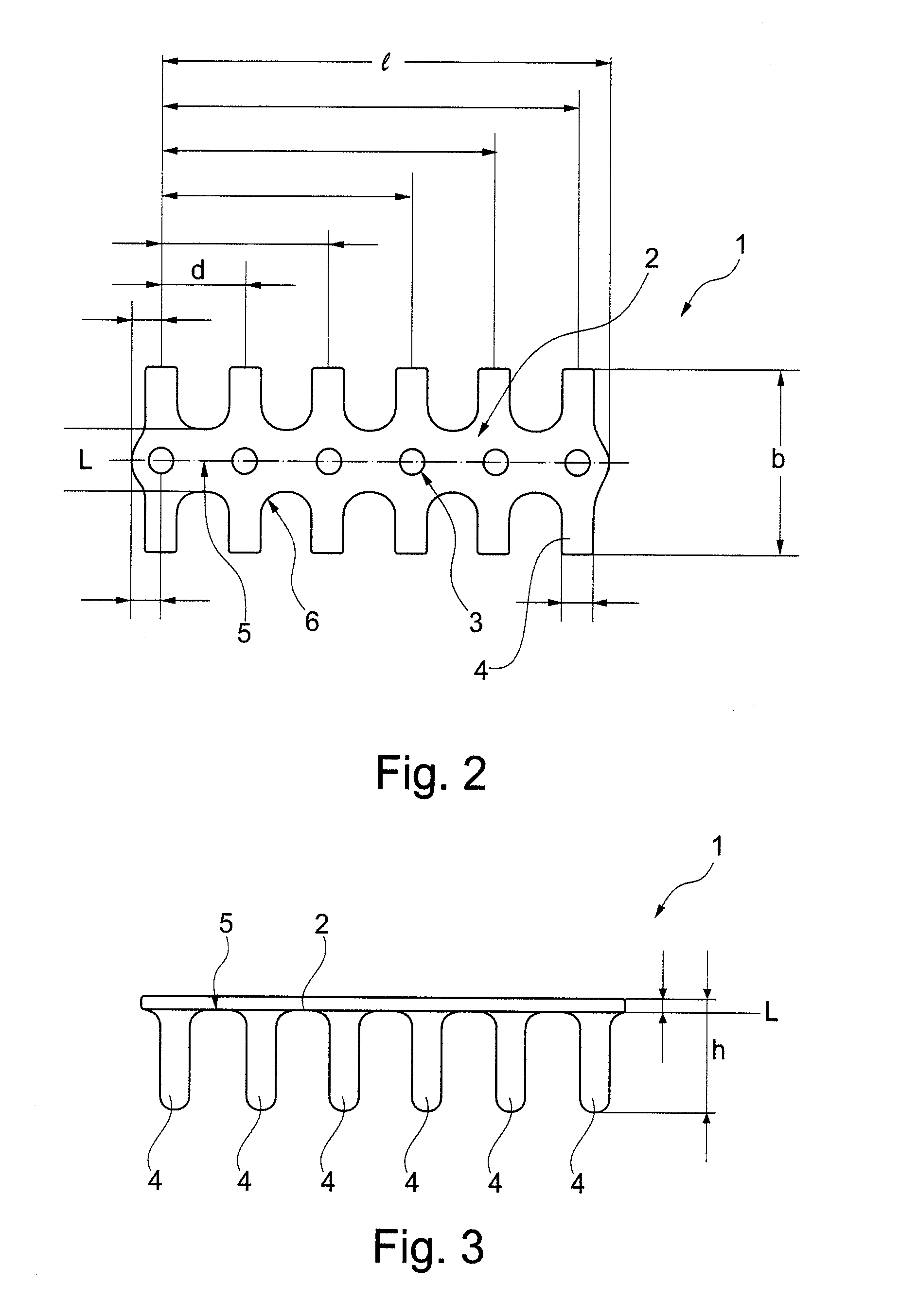
[0038]FIG. 2 is a schematic diagram of implant 1 in a plan view. Openings 3 and clamps 4 are formed or arranged at regular intervals d on fillet 2. The width b of the implant 1 is defined by the distance between the clamps 4 extending semicircularly into the plane of the figure.

[0039]The fillet 2 is formed as a thin strip of material in which the openings 3 are formed for engaging a bending tool, particularly a three-point pliers. Bending occurs on one hand in the drawing plane relative to the longitudinal axis L, especially in the areas 5 between the openings 3. In these areas 5, ...


PUM


Abstract

FIG. 1 shows an inventive implant 1. It has a central fillet 2 extending along a longitudinal axis L. The fillet 2 has openings 3 which are formed at regular intervals. At the level of the openings 3 and extending at right angles on both sides are clamps 4, which, when the implant is inserted, are brought into mutual engagement with a tubular bone and clamped to it. The fillet 2 is formed so as to be bendable in three-dimensions. It can be bent in two planes relative to the longitudinal axis L of the fillet 2 and torqued about the longitudinal axis L. Thus, a simple implant 1 with an overall regular structure is provided which can be cut with a cutting pliers to a desired length.

Description

FIELD OF THE INVENTION[0001]The invention relates to a device for the osteosynthesis and immobilization and stabilisation of tubular bones, comprising a carrier fillet extending in a first longitudinal direction, at least one first clamp extending laterally from the carrier fillet and a second clamp extending laterally from the carrier fillet, said second clamp being longitudinally offset from the first clamp.PRIOR ART[0002]After fractures or osteotomies of tubular bones, such as in the thorax region, the thorax needs to be stabilised to permit the bones to knit together. Stabilisation is mostly carried out conservatively, i.e. not invasively, from the outside. Nonetheless, the burden on the patient is significant. For example, the patient's breathing and mobility may be restricted. An improvement in his condition occurs only after a relatively long period of convalescence.[0003]Where treatment involves surgical intervention, it is standard practice to immobilize the bones with surg...

Claims


Application Information

Patent Timeline
Patent Type & Authority Applications(United States)
IPC IPC(8): A61B17/84
CPCA61B17/82A61B17/8076A61B17/8085
Inventor REISBERG, ERHARD
Owner REISBERG ERHARD
Why Eureka
Try Eureka