Device and method for determining a rheological property of mucus

a technology of rheological properties and devices, applied in the direction of liquid/fluent solid measurement, volume measurement, volume measurement, etc., can solve the problems of messy methods, inconvenient operation, and lack of user-friendly methods

Active Publication Date: 2011-05-05
KEN KEN
View PDF6 Cites 3 Cited by
  • Summary
  • Abstract
  • Description
  • Claims
  • Application Information

AI Technical Summary

Benefits of technology

[0027]Preferably, the host-unit comprises a repository for storing data associated with unit signals received from a plurality of remote processing units. Preferably, the host-unit is arranged for performing statistical analysis on the data stored in the repository. T

Problems solved by technology

This method is, however, generally regarded as messy.
This device has the disadvantage that it gives no indication of how high the viscosity of the mucus is, but only an indication whether or not the viscosity is above or below a predetermined threshold value.
This device has the disadvantage that the length of the thread as determined from the scale may depend largely on the ski

Method used


Image

  • Device and method for determining a rheological property of mucus
  • Device and method for determining a rheological property of mucus
  • Device and method for determining a rheological property of mucus

Examples


first embodiment

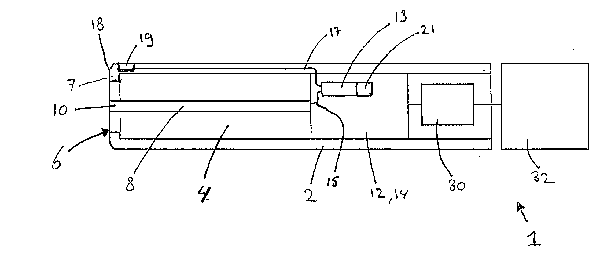
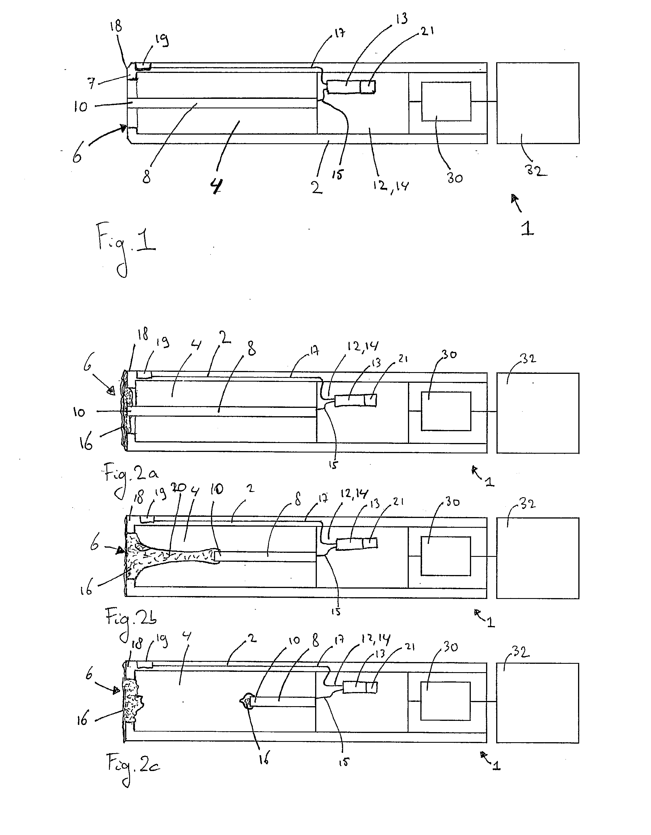
[0038]FIG. 1 shows an example of a device 1 for determining a rheological property, such as viscosity or threadability, of mucus according to the invention. In this example the device 1 comprises a housing 2 having a chamber 4 with an open end 6. At the open end a circumferential surface defines an opening. In this example, a cross section of the opening formed at the open end 6 is smaller than a cross section of the chamber 4. Hence, in this example, an inwardly extending flange 7 is formed. In this example, the housing 2 is substantially tubular. In FIG. 1, the device 1 further comprises a probe 8 extending within the housing 2. In this example the probe 8 extends substantially axially within the housing 2, in a longitudinal direction of the housing 2. The probe 8 has a tip 10 which is positioned near the open end 6 of the housing 2. The device 1 further comprises a displacement mechanism 12 for displacing the probe 8 with respect to the housing 2. In this example the displacement...

second embodiment

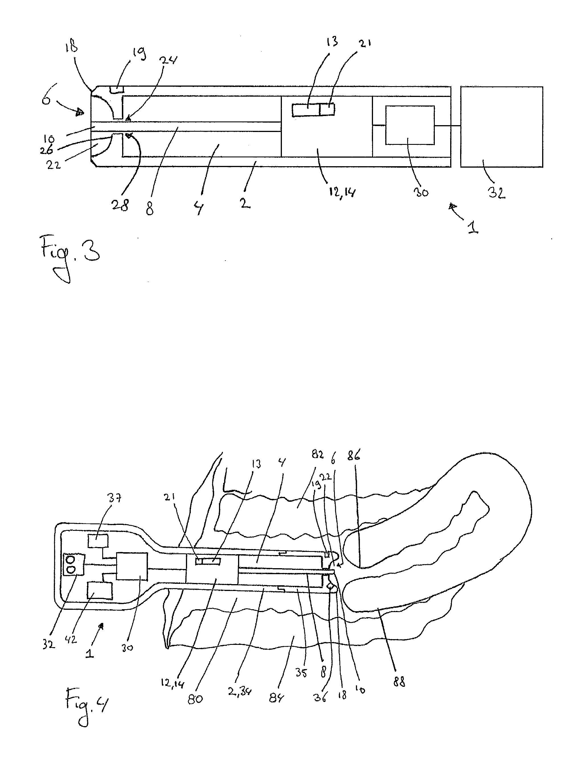
[0055]FIG. 3 shows an example of the device 1 according to the invention. In the example of FIG. 3, the open end 6 comprises a cup shaped recess 22. The tip 10 of the probe 8 extends through a hole 24 in a bottom 26 of the cup shaped recess 22. In this example an inner diameter of the hole 24 is larger than an outer diameter of the probe 8 at the location of the hole 24, such that a gap 28 is present between a wall of the hole 24 and the probe 8. A width of the gap 28 is chosen such that the mucus 16 is sucked into the gap 28 due to capillary action. As an example, the width of the gap 28 may be between 0.05 and 0.3 mm. In this example, the bottom of the recess 22 forms the inwardly extending flange 7 of the circumferential rim 18.

[0056]The working of the device 1 shown in FIG. 3 is identical to the wording of the device shown in FIGS. 1, 2a, 2b and 2c. The cup shaped recess 22 provides the advantage that the quantity of mucus 16 can more easily be brought into contact with the open...


PUM


Abstract

Device and method for determining a rheological property, such as viscosity or threadability, of mucus comprising a housing having a circumferential surface defining an opening for receiving a quantity of the mucus, a probe extending within the housing and having a tip for contacting at least a portion of the quantity of mucus, a displacement mechanism for displacing the tip of the probe with respect to the housing, and a measurement unit for measuring a displacement of the tip of the probe. The device and method are especially suitable for determining the rheological property of mammal cervical mucus for determining female fertility.

Description

FIELD OF THE INVENTION[0001]The invention relates to a device for determining a rheological property of mucus.[0002]More specifically the invention relates to a device for determining a rheological property of cervical mucus.BACKGROUND OF THE INVENTION[0003]The invention is related to detecting and predicting ovulation and / or a period of fertility in a female mammal, such as a female human. Knowledge about ovulation and / or the period of fertility allows family planning in the form of avoiding pregnancy, e.g. by practising sexual abstinence or other forms of birth control during the period of fertility. Alternatively, if so desired, the probability of conceiving can be increased by practicing sexual intercourse during the female fertile period.[0004]Ovulation and / or the period of fertility of a female can be predicted using a method referred to as natural family planning (NFP) sympto thermal method (STM). NFP / STM is a fertility awareness based (FAB) prediction method which uses as in...

Claims


Application Information

Patent Timeline
IPC IPC(8): G01N11/00G06F19/00
CPCA61B10/0012G01N2011/0066G01N11/04A61B2010/0022A61B2010/0016A61B2010/0019
Inventor MOONS, MATHIAS THEODORUS MARIA
Owner KEN KEN
Why Eureka
Try Eureka