Floating point multiplier with partial product shifting circuitry for result alignment

a technology of floating point multipliers and product shifting circuits, applied in the field of data processing systems, can solve the problems of undesirable additional hardware and delay, low performance solution, and the output of the adder from the two partial products is unlikely to be properly aligned for rounding, so as to achieve the effect of reducing the number of leading zeros

Active Publication Date: 2011-05-05
ARM LTD
View PDF15 Cites 27 Cited by
  • Summary
  • Abstract
  • Description
  • Claims
  • Application Information

AI Technical Summary

Benefits of technology

[0014]If the sum of the exponent value of the operand A and the exponent value of the operand B is less than the minimum permitted exponent value, then the shift amount determination circuitry may determine the shift amount to right shift the first partial product and the second partial product such that the exponent value of the result is the minimum permitted exponent value. The shifting circuitry will thus have the effect of producing a subnormal result. If the right shift applied to the first partial product and the second partial product is greater than an amount that results in the fractional value of the result being guaranteed to be zero, then the result will ...

Problems solved by technology

A problem with the above is how to deal with subnormal results.
This is a low performance solution.
If subnormal numbers are to be handled in hardware, then a problem is that the output of ...

Method used


Image

  • Floating point multiplier with partial product shifting circuitry for result alignment
  • Floating point multiplier with partial product shifting circuitry for result alignment
  • Floating point multiplier with partial product shifting circuitry for result alignment

Examples


example b

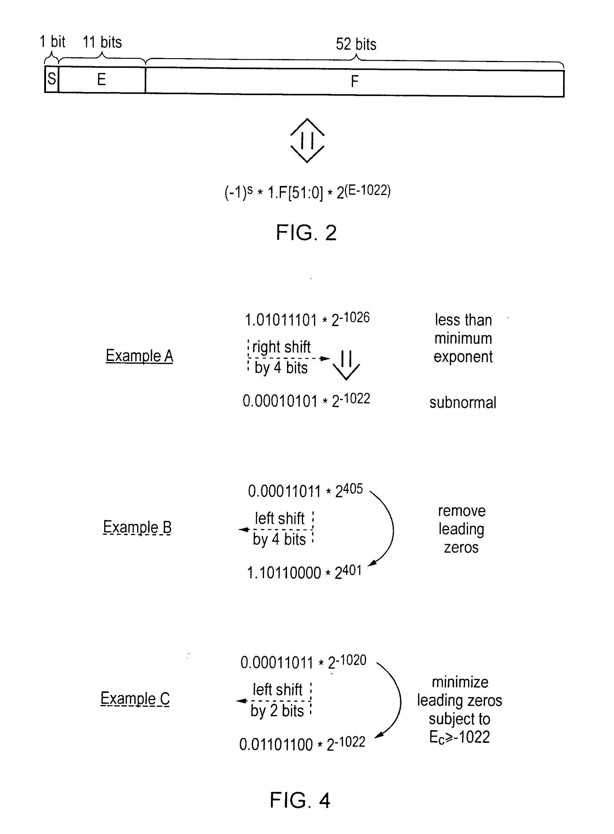
[0058]Example B of FIG. 4 illustrates a result value generated when one of the input operand A and the input operand B is subnormal. In this case the result significand first calculated would be subnormal. Providing the limit on the minimum size of the exponent of the result C will not be exceeded then these leading zeros can be removed and the significand returned to a normal value by left shifting four bit positions. This is illustrated in FIG. 4 The bit values shifted in to the significand as it is left shifted may be taken from the low order portion of the effectively 106-bit result which is calculated as discussed above.

example c

[0059 of FIG. 4 illustrates a situation similar to that of Example B except that in this case the exponent value is close to the minimum exponent value and accordingly only a left shift of two bit positions is permitted in order that the minimum exponent value limit is not breached.

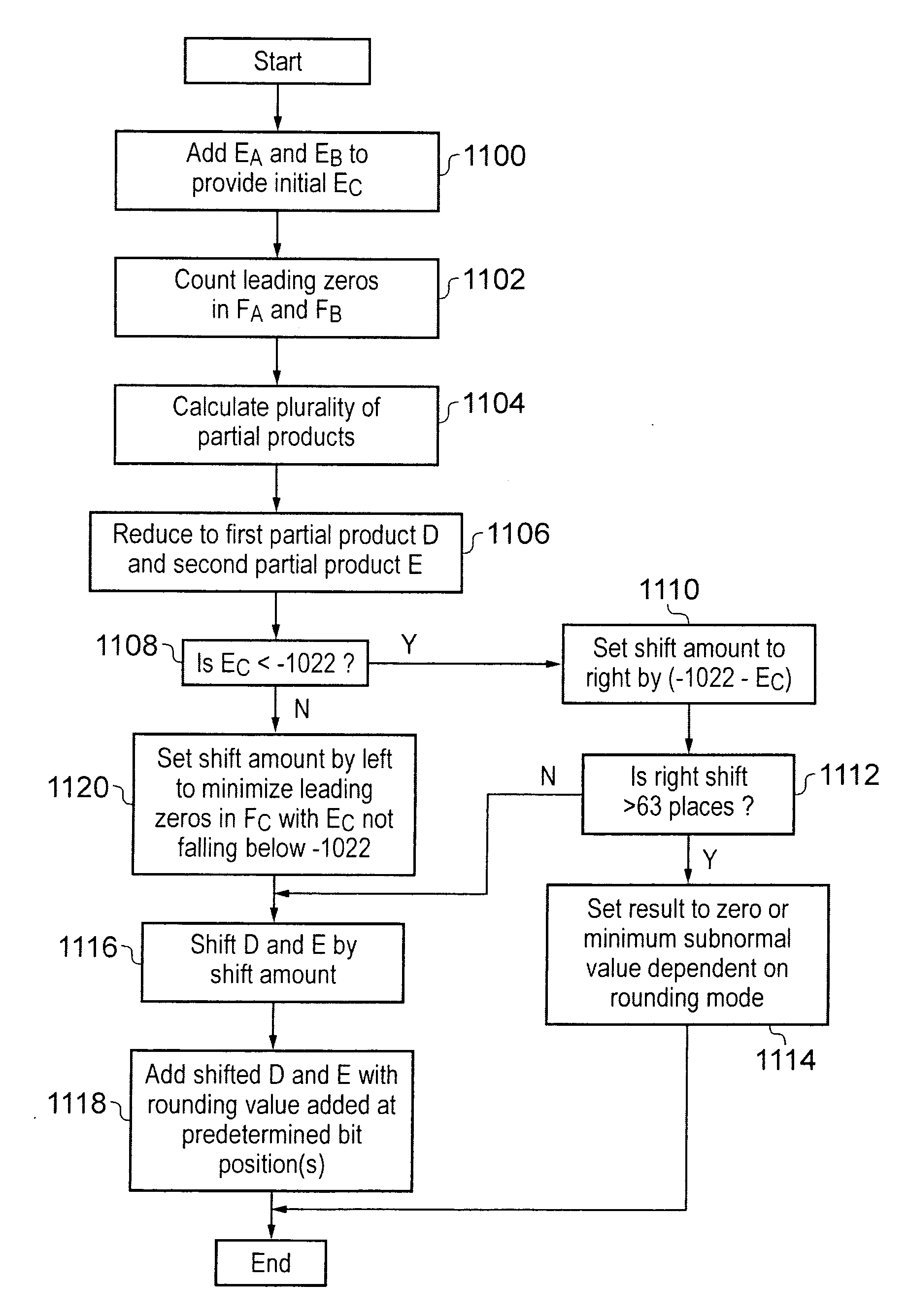
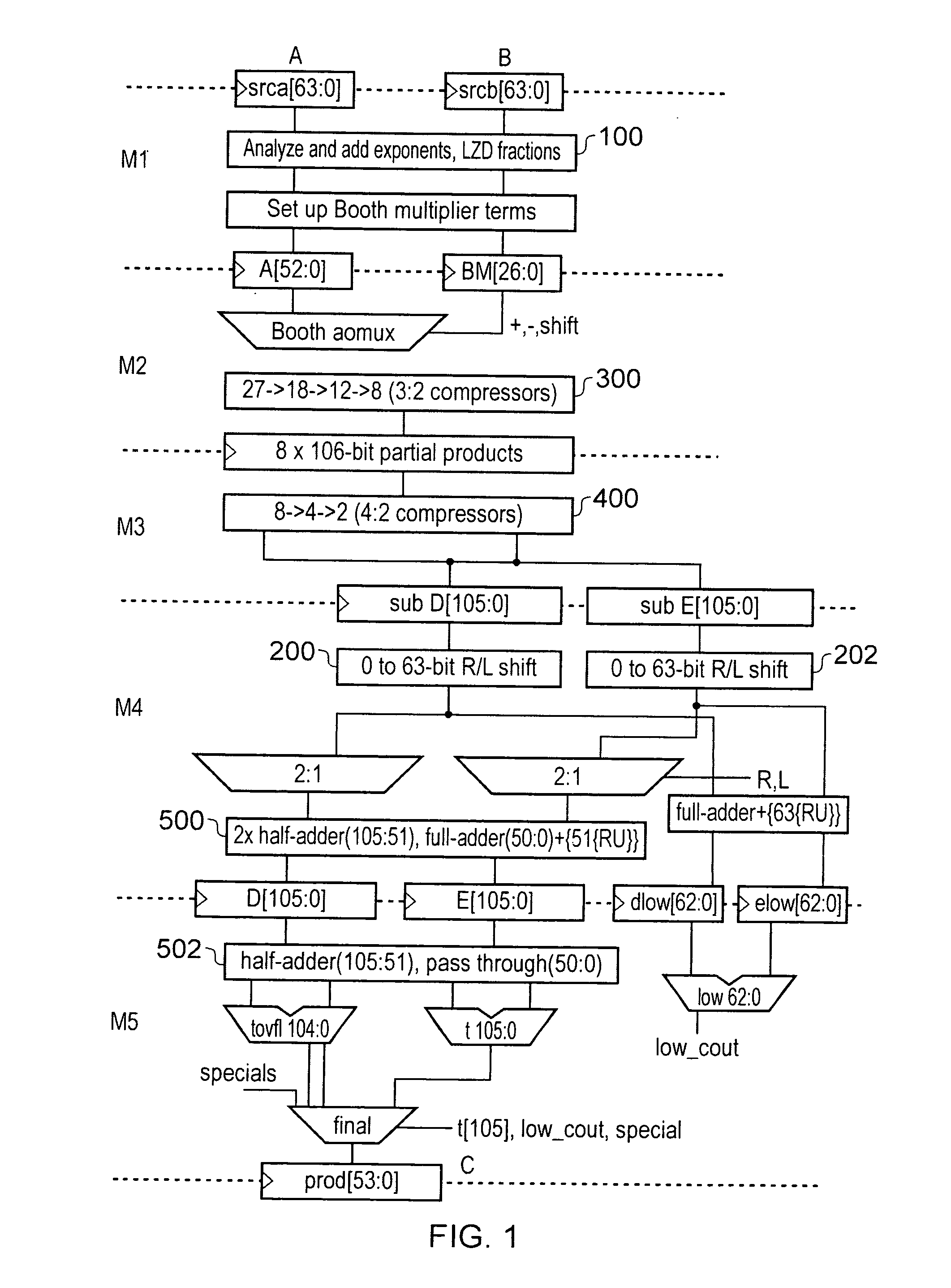
[0060]FIG. 5 is a flow diagram schematically illustrating the operation of the circuit of FIG. 1. At step 1100 the shift value determining circuitry adds the exponents EA and EB of the input operand A and the input operand B to provide an initial value of the result exponent EC. At step 1102 the shift value determining circuitry counts the number of leading zeros in the fractional values FA and FB of the input operands A and B. At step 1104 the multiplier calculates the plurality of partial products. At step 1106 the reducing circuitry comprised of 3:2 compressors 300 and 4:2 compressors 400 reduces the plurality of partial products down to a first partial product D and a second partial product E.

[0061]At...


PUM


Abstract

A floating point multiplier includes a data path in which a plurality of partial products are calculated and then reduced to a first partial product and a second partial product. Shift amount determining circuitry 100 analyses the exponents of the input operands A and B as well as counting the leading zeros in the fractional portions of these operands to determine an amount of left shift or right shift to be applied by shifting circuitry 200, 202 within the multiplier data path. This shift amount is applied so as to align the partial products so that when they are added they will produce the result C without requiring this to be further shifted. Furthermore, shifting the partial products to the correct alignment in this way in advance of adding these partial products permits injection rounding combined with the adding of the partial products to be employed for cases including subnormal values.

Description

BACKGROUND OF THE INVENTION[0001]1. Field of the Invention[0002]This invention relates to the field of data processing systems. More particularly, this invention relates to floating point multipliers for use within data processing systems.[0003]2. Description of the Prior Art[0004]It is known to provide data processing systems with the ability to manipulate floating point numbers. The hardware mechanisms for providing floating point multiplication typically use the multiplier and multiplicand to generate numerous partial products. Various forms of carry-save adders are then used to reduce the partial products to two partial products. These final two partial products are then added before being rounded to produce the final product result.[0005]A problem with the above is how to deal with subnormal results. Subnormal results are where the exponent value has the minimum permitted value and the significand is less than one, e.g. 0.001101. The nature of subnormal numbers is familiar to t...

Claims


Application Information

Patent Timeline
IPC IPC(8): G06F7/487G06F5/01G06F7/485G06F7/552
CPCG06F7/4876
Inventor LUTZ, DAVID RAYMOND
Owner ARM LTD
Why Eureka
Try Eureka