
Method and device for transferring heat

a heat transfer and heat energy technology, applied in photovoltaics, energy-efficient heating/cooling, sustainable buildings, etc., can solve the problems of low coefficient of performance, affecting the environment, and affecting the efficiency of energy consumption, and achieve the effect of small size and larger coefficient of performan

Inactive Publication Date: 2011-05-12
OKSANEN JANI +1
View PDF9 Cites 6 Cited by
  • Summary
  • Abstract
  • Description
  • Claims
  • Application Information

AI Technical Summary

Benefits of technology

[0010]The mentioned device may be a device using photons to transfer heat, that is, a photonic heat pump. The photonic heat pump according to certain embodiments is a solid state heat pump suitable for both cooling and heating applications. Its advantages compared to compressor based heat pumps are small size and the lack of moving parts and refrigerants. In addition it may reach a larger coefficient of performance than other solid state heat pumps.

Problems solved by technology

The weaknesses of these solutions are large size, harmful impact on the environment and wearing out of the moving parts for the mechanical heat pumps, and in the case of thermoelectric heat pumps, the low coefficient of performance.

Method used


Image

  • Method and device for transferring heat
  • Method and device for transferring heat

Examples


Embodiment Construction

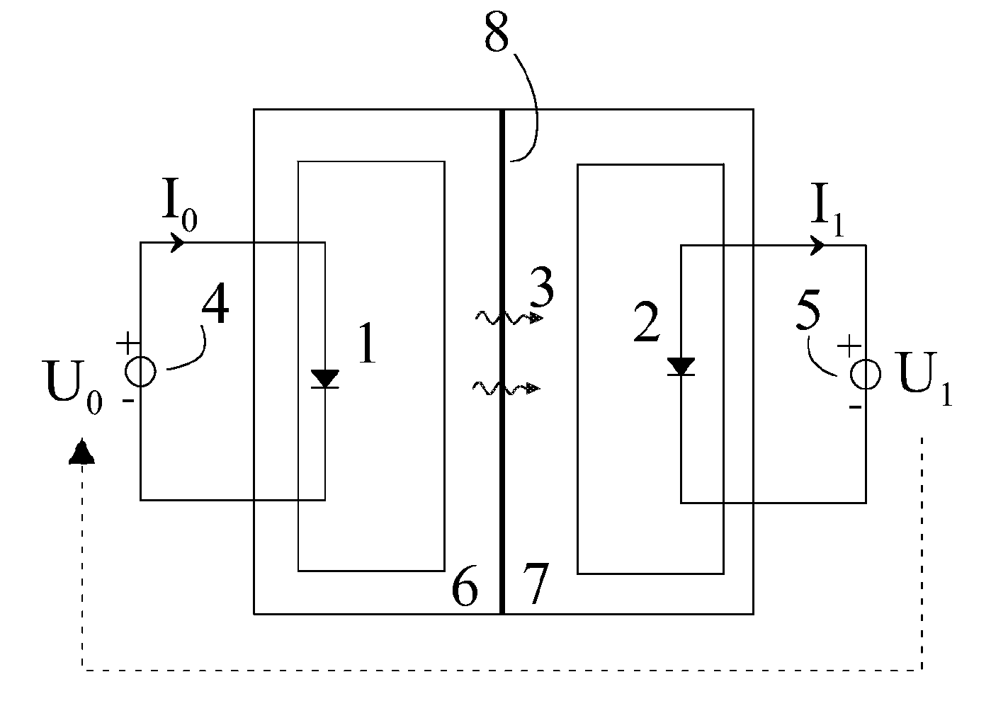
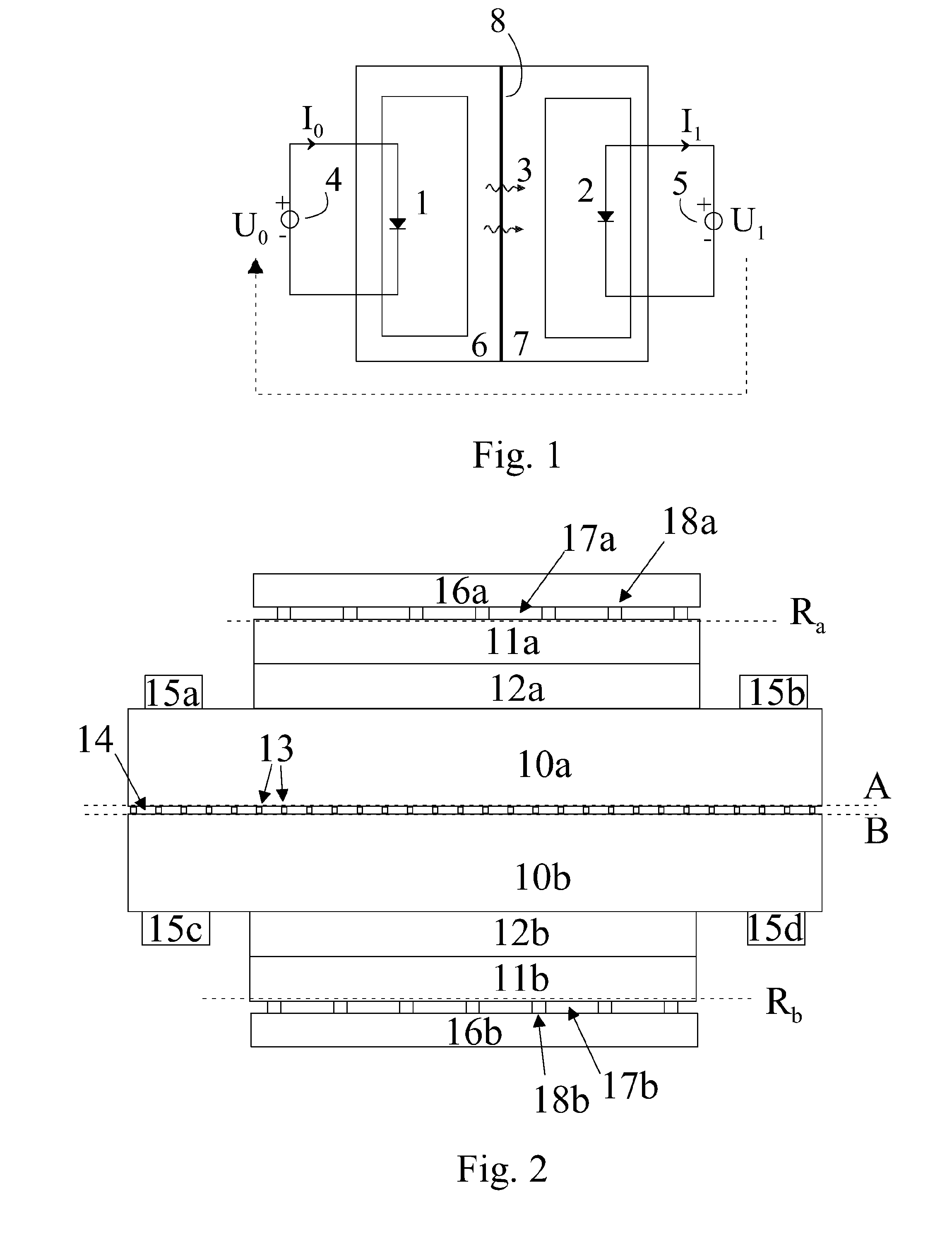
[0015]In the following, examples of an operation principle and a structure of a heat pump operating with the aid of light in accordance with aspects of the disclosed embodiments are described. It is to be noted that, instead of light, the heat pump may transfer heat with the aid of other electromagnetic radiation.

[0016]In FIG. 1, an element 1 emitting radiation emits radiation 3 with the aid of an external energy source 4. Element 1 can include for example a light emitting diode that emits light by electroluminescence, and the external energy source 4 can be a voltage source U0, that provides a current 10 for the light emitting diode through an electrical circuit of FIG. 1. The emitted radiation 3 is transferred to the element 2 absorbing radiation, where a part of the energy included in the radiation is released as heat energy and a part is recovered in an easily exploited form of energy, e.g., electrical or mechanical energy, in an external element 5. The element 2 can be for exam...


PUM


Abstract

A method and device for transferring heat in a heat pump, where heat energy is transferred with the aid of light or other electromagnetic radiation from an element (1) emitting radiation to an element (2) absorbing radiation in a direction opposite to the direction defined by the second law of thermodynamics and in which a part of the energy of the absorbed radiation is converted back to an exploitable form of energy, like electrical or mechanical energy.

Description

BACKGROUND[0001]1. Field[0002]The aspects of the disclosed embodiments relate in general to energy transfer, and particularly to transferring heat energy with the aid of electromagnetic radiation, such as light.[0003]2. Brief Description of Related Developments[0004]Known heat transfer methods conventionally use various refrigerants (for example compressor based solutions in refrigerators) or electric current (Peltier elements). The weaknesses of these solutions are large size, harmful impact on the environment and wearing out of the moving parts for the mechanical heat pumps, and in the case of thermoelectric heat pumps, the low coefficient of performance.SUMMARY[0005]According to a first embodiment, a method is provided where heat energy is transferred with the aid of electromagnetic radiation generated in a structure from an element emitting radiation to an element absorbing radiation. The electromagnetic radiation mediating the heat energy is generated by electroluminescence and...

Claims


Application Information

Patent Timeline
Patent Type & Authority Applications(United States)
IPC IPC(8): F25B21/00H01J40/14
CPCF25B21/00H02S10/30Y02B30/66H01L31/167Y02B30/00Y02E10/50F25B23/003G05D23/1919H01L33/00
Inventor OKSANEN, JANITULKKI, JAAKKO
Owner OKSANEN JANI
Learn More