Variable valve device for internal combustion engine

Inactive Publication Date: 2011-05-12
MITSUBISHI MOTORS CORP
View PDF7 Cites 3 Cited by
  • Summary
  • Abstract
  • Description
  • Claims
  • Application Information

AI Technical Summary

Benefits of technology

[0010]The width of fluctuation of torque on the intake camshaft varies depending on the relative displacement of the inner camshaft relative to the outer camshaft. Greater fluctuation of torque leads to greater likelihood of transition from lubricant's fluid lubrication to boundary lubrication, and thus, increased frict

Problems solved by technology

Greater fluctuation of torque leads to greater likelihood of transition from lubricant's flu

Method used


Image

  • Variable valve device for internal combustion engine
  • Variable valve device for internal combustion engine
  • Variable valve device for internal combustion engine

Examples


Example

[0018]Referring to the drawings attached, an embodiment of the present invention will be described.

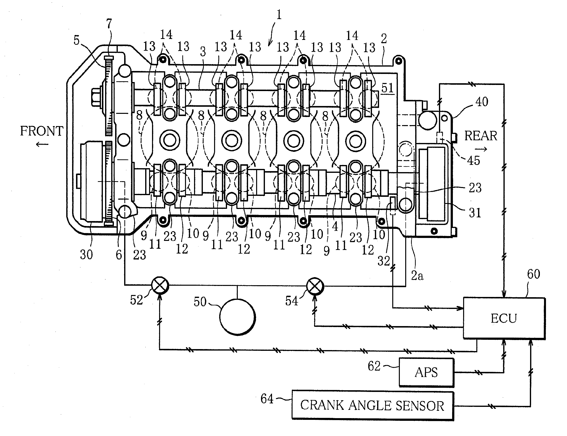
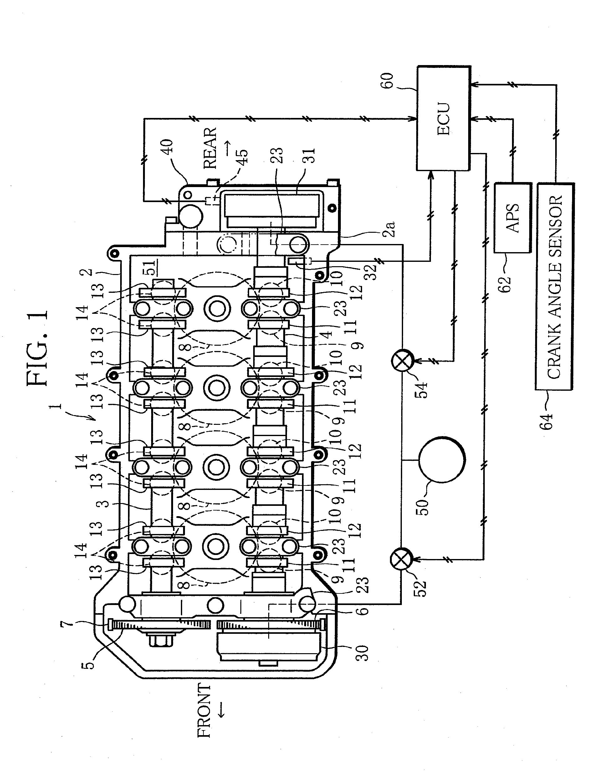
[0019]FIG. 1 schematically illustrates the construction of a variable valve device for an internal combustion engine according to the present invention. More particularly, FIG. 1 is a top view showing the internal structure of a cylinder head 2 of an engine 1.

[0020]The engine 1 is, for example an in-line four-cylinder engine with a DOHC valve train. As seen in FIG. 1, an exhaust camshaft 3 and an intake camshaft 4, rotatably supported inside the cylinder head 2, have cam sprockets 5, 6 mounted thereon, respectively. The cam sprockets 5, 6 are connected to a crankshaft, not shown, by a chain 7.

[0021]For each cylinder 8 of the engine 1, two intake valves 9, 10 and two exhaust valves 14, 14 are provided. On the intake camshaft 4, first and second intake cams 11, 12 are provided alternately, and the two intake valves 9, 10 for each cylinder 8 are driven by the first and second intake cams ...


PUM


Abstract

A variable valve device for an internal combustion engine includes a cam phase variable mechanism for varying a phase difference (split) between first and second intake cams. Under predetermined operating conditions of the internal combustion engine, the second intake cam is controlled to take a phase (split) (S1) which is within a predetermined pumping-loss reduction operation phase range and entails a minimum fluctuation (oscillation width) of drive torque on an intake camshaft.

Description

BACKGROUND OF THE INVENTION[0001]1. Field of the Invention[0002]This present invention relates to a variable valve device for internal combustion engines, and more particularly, techniques for optimizing valve opening / closing timings of intake and exhaust valves.[0003]2. Description of the Related Art[0004]In recent years, more and more internal combustion engines (engines) have come to be equipped with cam phase variable mechanisms as a variable valve device for varying valve opening / closing timings (cam phases). Also, techniques have been developed whereby the cam phase variable mechanisms are applied to an engine having each cylinder provided with a plurality of intake valves and the valve opening / closing timings of all intake valves as well as only some of the intake valves are varied (split) in accordance with the operating condition of the engine (Japanese Laid-open Patent Publication No. 2009-144521).[0005]Where the valve opening / closing timings of only some of the intake val...

Claims


Application Information

Patent Timeline
IPC IPC(8): F01L1/344
CPCF01L1/34F01L1/3442F01L2001/0473Y02T10/18F01L2001/34489F01L2800/06F02D13/0238F01L2001/0478Y02T10/12
Inventor MURATA, SHINICHI
Owner MITSUBISHI MOTORS CORP
Why Eureka
Try Eureka