Organic electroluminescence element and manufacturing method thereof

Active Publication Date: 2011-05-12
JOLED INC
View PDF19 Cites 15 Cited by
  • Summary
  • Abstract
  • Description
  • Claims
  • Application Information

AI Technical Summary

Benefits of technology

[0020]In the present invention, since a part of the contour of each of the apertures is of a shape that includes curves, which bulge inwards of the aperture, and cusps, each of which is a connection point of adjacent curves, the mechanical strength (particularly the collapse strength) of the bank improves, and is particularly suitable for when the bank is used as a

Problems solved by technology

However, there is the problem that the shape, in which the corners of the apertures are beveled in order to ensure ink fillability, is not necessarily sufficient to meet the demand for ensuring the

Method used


Image

  • Organic electroluminescence element and manufacturing method thereof
  • Organic electroluminescence element and manufacturing method thereof
  • Organic electroluminescence element and manufacturing method thereof

Examples


Example

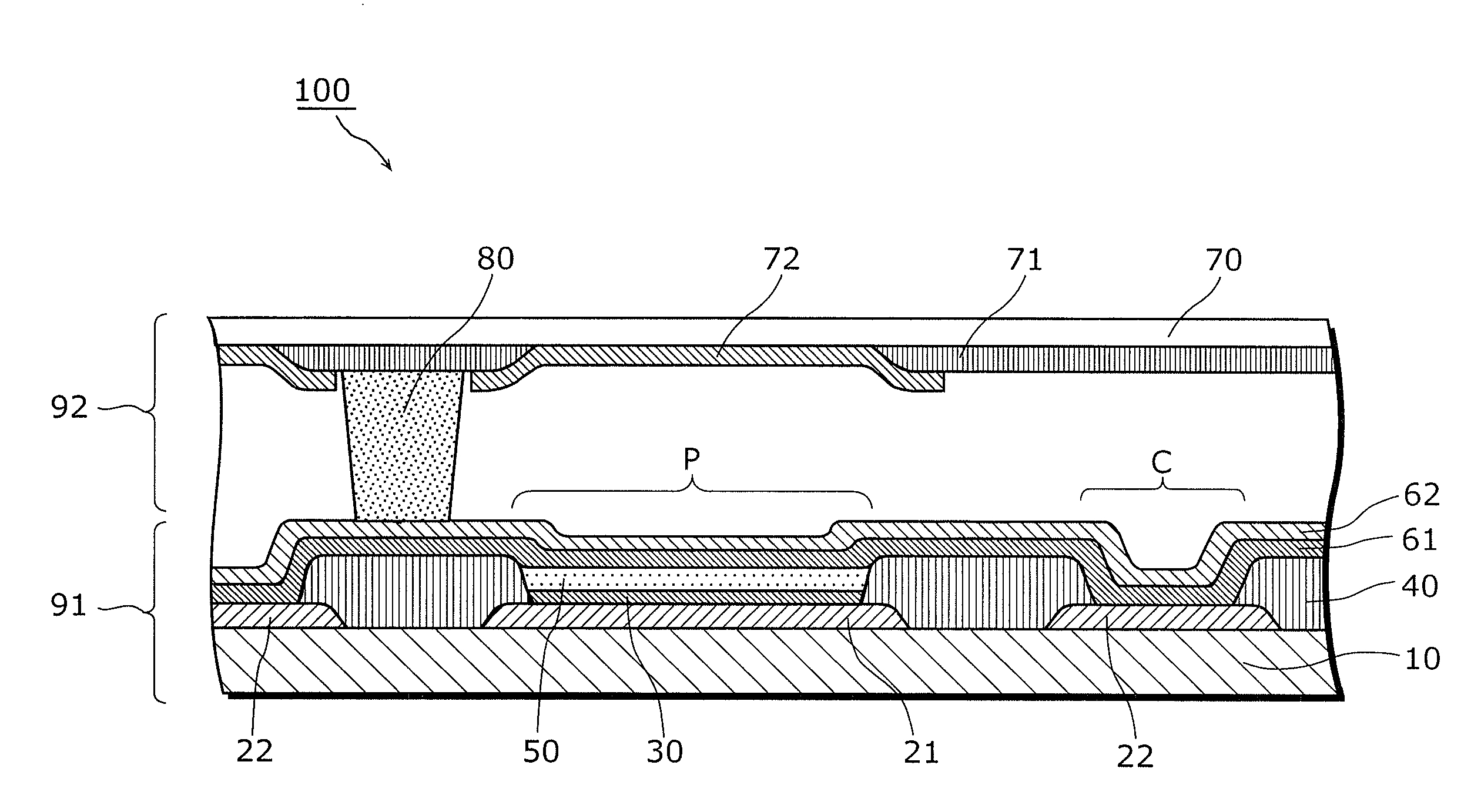
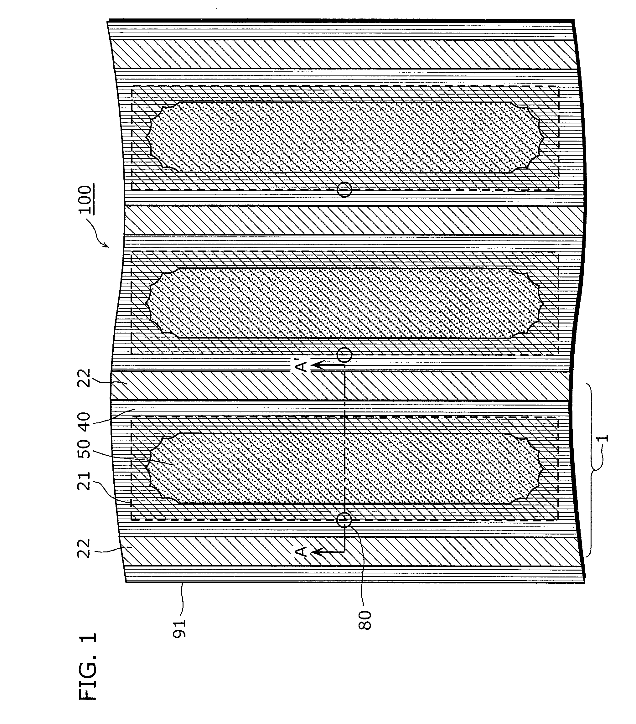
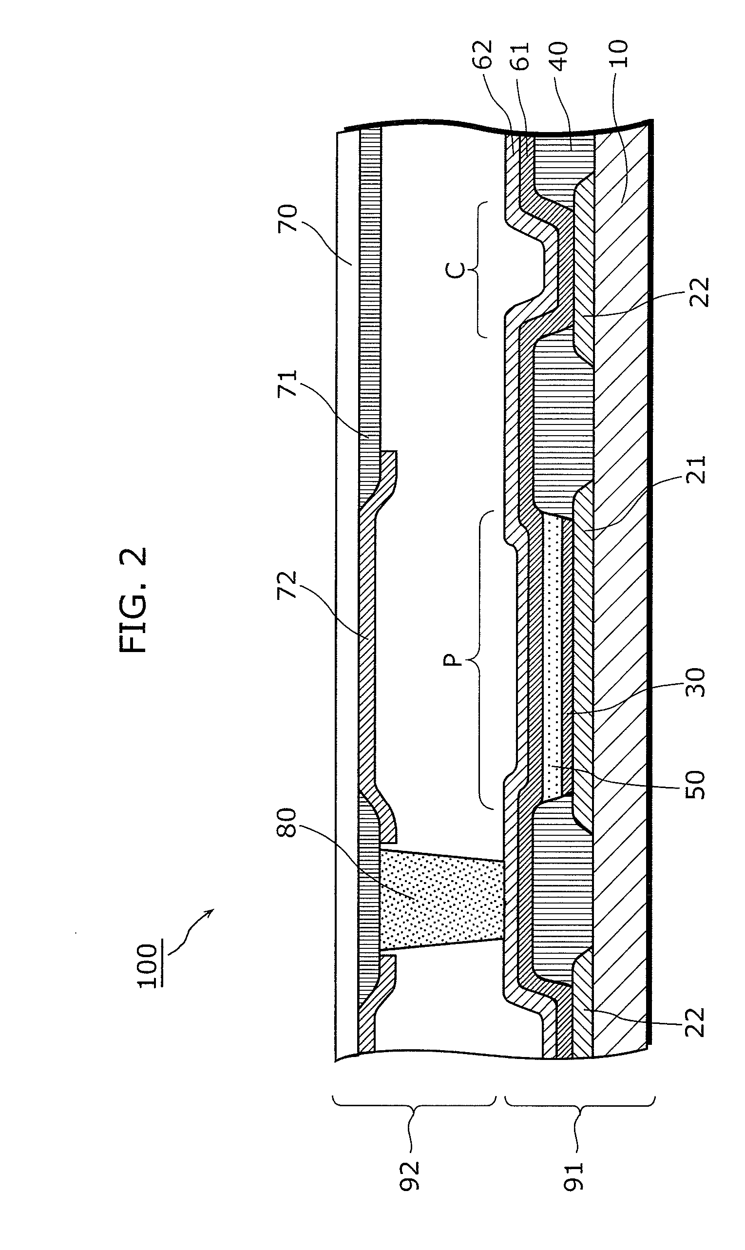
[0030]In one implementation, the organic electroluminescence element according to the present invention includes: pixel electrodes; a bank which is placed between adjacent ones of the pixel electrodes and includes apertures each of which corresponds to one of the pixel electrodes; an organic luminescent layer which is placed within each of the apertures; and an upper electrode which is placed above the bank and the organic luminescent layer, wherein a shape of a part of a contour of each of the aperture, and the cusps each being a connection point of adjacent ones of the curves.

[0031]The present invention is characterized in that the respective apertures of the bank into which ink is applied are of a shape that is defined by a contour including curves bulging inwards of the aperture and cusps each of which is a connection point of adjacent curves. Such contour shape of the apertures enables the improvement of the mechanical strength (particularly, the collapse strength) of the bank,...


PUM


Abstract

An organic luminescence includes pixel electrodes. Banks are each generally between adjacent ones of the pixel electrodes. The banks define apertures that each correspond to one of the pixel electrodes. An organic luminescent layer is within each of the apertures, and an upper electrode is above the banks and the organic luminescent layer. At least a portion of a periphery of each of the apertures includes curved portions and cusps. The curved portions are concave, and adjacent ones of the curved portions define each of the cusps.

Description

CROSS REFERENCE TO RELATED APPLICATION[0001]This is a continuation application of PCT Application No. PCT / JP2009 / 006026, filed on Nov. 11, 2009, designating the United States of America, the disclosure of which, including the specification, drawings, and claims, is incorporated herein by reference in its entirety.BACKGROUND OF THE INVENTION[0002]1. Field of the Invention[0003]The present invention relates to an organic electroluminescence (hereafter referred to as organic EL) element and a manufacturing method thereof.[0004]2. Description of the Related Art[0005]Organic EL display devices are luminescence display devices which utilize electric field luminescence phenomenon of an organic compound, and are being put into practical use as compact display devices used in cellular phones and so on.[0006]An organic EL display device is configured by placing organic EL elements in an array, on a substrate. Such organic EL elements allow independent luminescence-production control on a per ...

Claims


Application Information

Patent Timeline
IPC IPC(8): H01L51/52H01L51/56
CPCH05B33/10H01L27/3246H10K59/122H10K2102/301
Inventor OOSAKO, TAKASHI
Owner JOLED INC
Why Eureka
Try Eureka