
Energy absorber with lobes providing uniform pedestrian impact

Active Publication Date: 2011-05-12
VOLKSWAGEN AG +1
View PDF83 Cites 26 Cited by
  • Summary
  • Abstract
  • Description
  • Claims
  • Application Information

AI Technical Summary

Benefits of technology

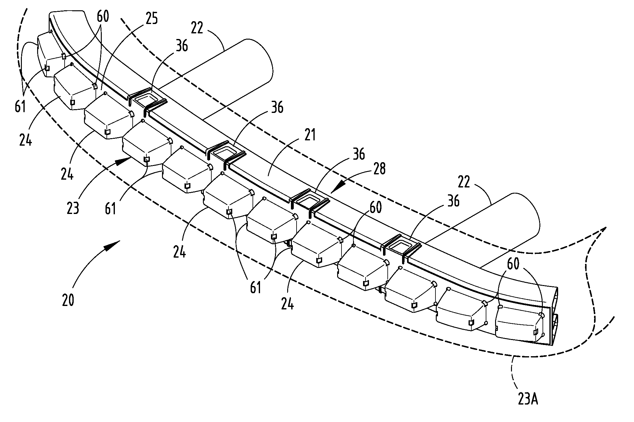
[0007]In one aspect of the present invention, a bumper system is provided for a vehicle having a longitudinal direction, the bumper system having corners defined by vertical planes oriented at 60° to the longitudinal direction and engaging a front of the bumper system, the bumper system further having a “bumper test area” defined about 66 mm inboard of each of the corners but excluding a center region of 250 mm of the bumper system. The bumper system includes a bumper reinforcement beam configured for attachment to a vehicle frame, and an energy absorber positioned on a face of the beam. The energy absorber includes a plurality of spaced-apart hollow crush lobes in the bumper test area that are configured to crush and absorb energy during a pedestrian impact. The lobes are configured to provide a uniform impact energy absorption during crush of within + / −30% of a desired average impact energy absorption force-deflection profile for impact intrusions that crush the crush lobes at least 10 mm in longitudinal locations along a length of the “bumper test area”. By this arrangement, the bumper system provides for pedestrian safety regardless of a specific location where a pedestrian's leg strikes the energy absorber.
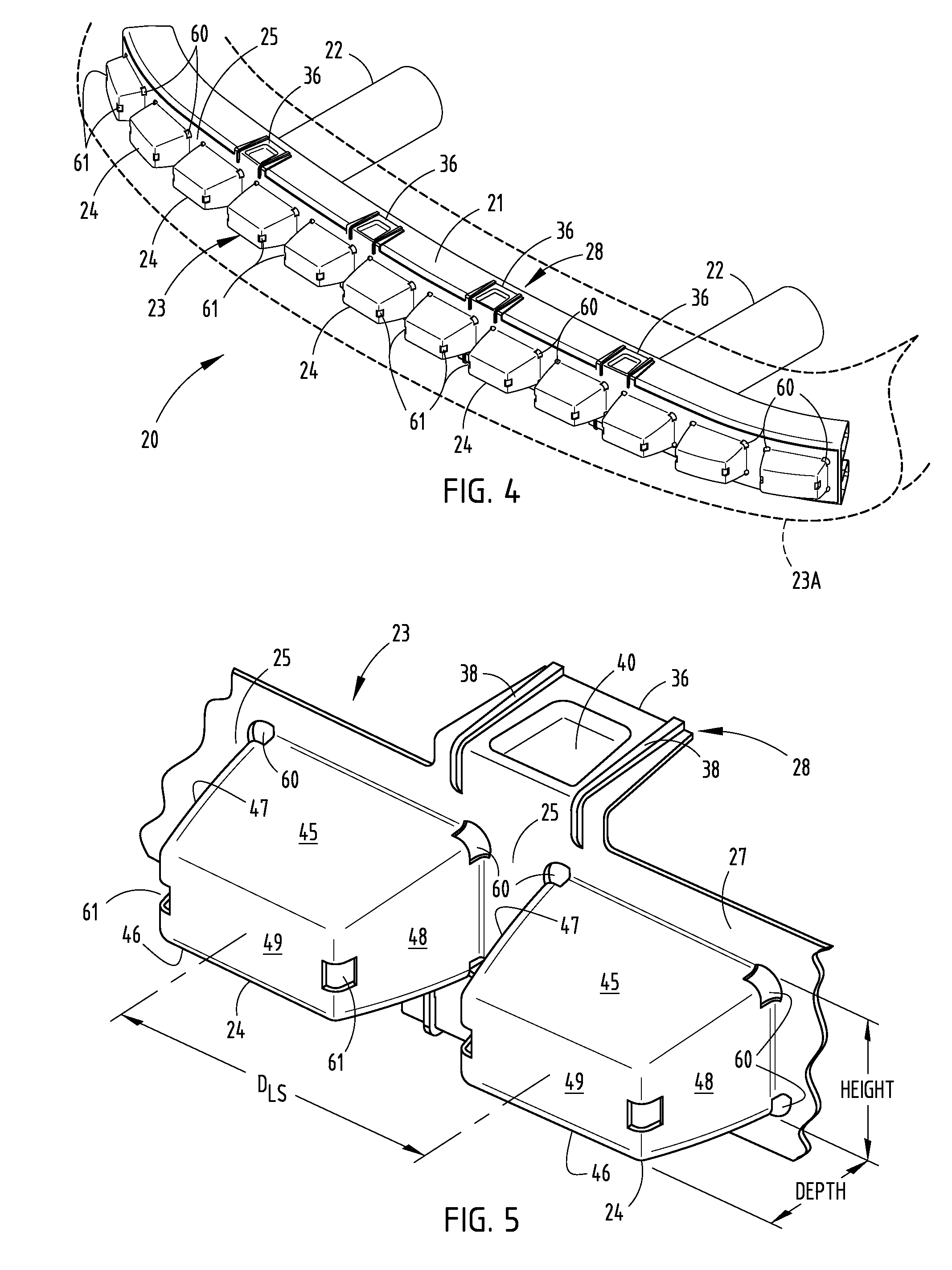
[0009]In another aspect of the present invention, an energy absorber is configured to be positioned on a face of a beam. The energy absorber comprises a base flange, and at least one hollow lobe extending from the base flange and having top and bottom shear walls and vertical shear walls that join to define four corners. There is at least one aperture strategically located at a base of each corner, the at least one aperture extending partially around each respective corner and into the associated adjacent walls to reduce columnar strength of the respective corner. The shear walls and apertures are shaped and sized to cause a predictable and uniform impact resistance to a pedestrian's leg regardless of a specific location where the pedestrian's leg strikes the energy absorber, the impact resistance being uniform to within + / −30% of a desired force deflection profile during impacts crushing more than 10 mm the at least one hollow lobe to absorb energy.
[0011]In another aspect of the present invention, a method comprising steps of providing an energy absorber with a base flange configured to engage a support structure and including spaced-apart hollow lobes extending from the base flange and defining a test area; the lobes each including shear walls configured to crush and absorb energy along a force deflection profile when impacted by a pedestrian-leg-simulating impactor for an intrusion stroke causing collapse of the hollow lobes of at least 10 mm. The method further includes tuning the crush lobes of the energy absorber to improve uniformity of energy absorption to within + / −30% of a desired average energy absorption profile regardless of a specific location of impact by the impactor along the test area of the energy absorber by forming at least one of apertures and external ribs on the crush lobes, where the ribs, if present, are located on shear walls of the crush lobes and where the apertures, if present, are located at corners formed by adjacent ones of the shear walls, to thus provide uniform performance and pedestrian safety regardless of a specific location where a pedestrian's leg strikes the energy absorber.

Problems solved by technology

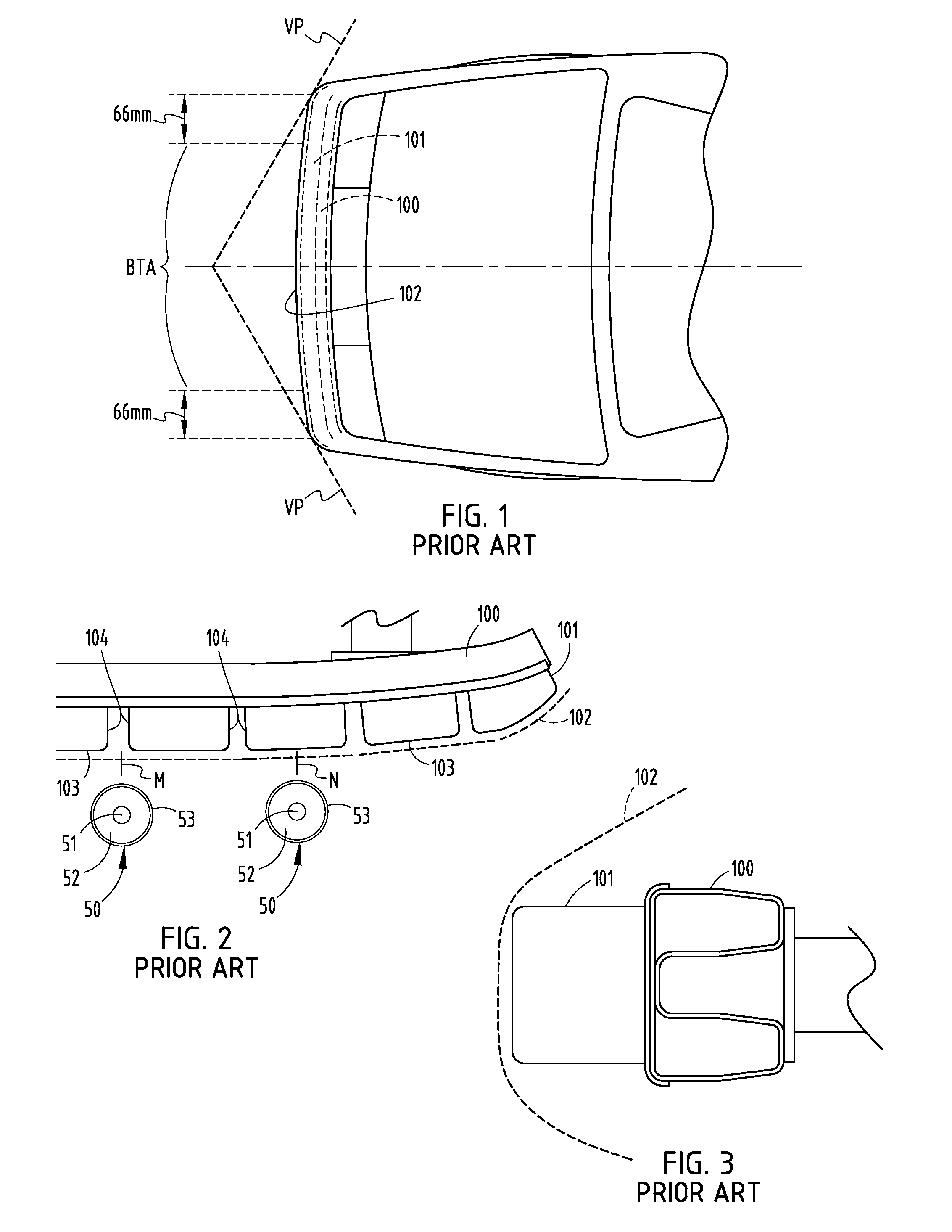
However, when impacted at location N (i.e. the impact is centered on a single lobe), the leg receives a relatively lower impact resistance (i.e. virtually no impact resistance from any vertical shear wall).
This is because the lobe is elongated, such that there is no close vertical shear wall to location N. This condition results in inconsistent and unpredictable impact energy absorption when a pedestrian is impacted.
The pedestrian impact criteria primarily apply to a front section of a bumper system located between corners of the vehicle, because that is where pedestrian impacts are often struck and cause greatest injury.

Method used


Image

  • Energy absorber with lobes providing uniform pedestrian impact
  • Energy absorber with lobes providing uniform pedestrian impact
  • Energy absorber with lobes providing uniform pedestrian impact

Examples


Embodiment Construction

[0032]In the present description, various terms are used to facilitate a description, such as height, width, length, upper, lower, right, left, and etc. These terms are used to facilitate the description, but are not intended to be unnecessarily limiting. Further, it is noted that sometimes the terms refer to the part in a vehicle-mounted orientation (where the lobes face horizontally / forwardly), while other times the terms are used to refer to the energy absorber laying on a rest surface such as a table (with the lobes facing upwardly).

[0033]A vehicle bumper system 20 (FIGS. 4-6) includes a reinforcement beam 21 mounted to a vehicle frame by mounts 22, and an energy absorber 23 on its face, covered by a fascia (see the fascia 23A in FIG. 2). The illustrated energy absorber 23 (FIGS. 6-10) is injection molded of polymeric material and includes hollow longitudinally-spaced energy-absorbing lobes 24 (also called “crush boxes”) and co-planar straps 25 (coplanar with and forming part of...


PUM


Abstract

A bumper system includes an injection molded energy absorber of polymeric material having hollow longitudinally-spaced lobes configured to crush and absorb energy during a pedestrian impact, and straps interconnecting adjacent lobes. The lobes are particularly sized and dimensioned, including potentially external ribs and / or apertures in corners, to provide a relatively uniform impact energy absorption during an impact stroke during crush of the shear walls of the lobes, such as within + / −30% or more preferably within + / −20% of a desired amount regardless of a specific location of impact, along a selected center portion of the energy absorber. A reason for the uniformity is to promote pedestrian safety regardless of the specific location where a pedestrian's leg strikes the energy absorber.

Description

[0001]This application claims benefit under 35 U.S.C. Section 119(e) of provisional application Ser. No. 61 / 258,653, filed Nov. 6, 2009, entitled ENERGY ABSORBER WITH LOBES REDUCING PEDESTRIAN INJURY, the entire contents of which are incorporated herein in their entirety.BACKGROUND[0002]The present invention relates to vehicle bumper systems having energy absorbers, where the energy absorbers have hollow crush lobes constructed to collapse upon impact at predetermined rates of resistance and energy absorption.[0003]Modern vehicle bumpers often include polymeric energy absorbers positioned on a face of a metal reinforcement beam and that are adapted to absorb impact energy. These energy absorbers often have forwardly-projecting hollow lobes (also called “crush boxes”) that are elongated horizontally and where adjacent lobes are interconnected by straps. The lobes are often hollow “box shaped” structures that, when in a vehicle mounted position, include top and bottom horizontal shear...

Claims


Application Information

Patent Timeline
IPC IPC(8): B60R19/34
CPCB60R19/18B60R2021/343B60R2019/1893B60R2019/1873B60R21/34B60R2019/1833B60R2021/0051
Inventor RALSTON, DANIELREVANKAR, VIDYAKULKARNI, AMIT ASHOKEVANS, DARININSEL, OLAFGHOZZI, YASSINEBESCH, ALEXANDERKNOKE, OLIVERNGUYEN, NGOC-DANG
Owner VOLKSWAGEN AG
Learn More