[0005]In the above-described related art, a signal current corresponding to a signal electric potential can be supplied to the organic EL device by applying the signal electric potential, which is generated based on a video signal of a video to be displayed, to the gate terminal of the driving transistor. Accordingly, the display device can allow the organic EL device to emit light in accordance with the magnitude of the signal current at the signal
voltage. In such display devices, as a technique for increasing the number of gray scales of the luminance of the organic EL device, a method in which the number of steps of the signal electric potential generated based on the video signal is increased may be considered. However, when the number of steps of the signal electric potential is increased, the scale of a signal driver that generates the signal electric potential is necessarily increased. Therefore, there is a problem that the manufacturing cost is increased.
[0006]Thus, it is desirable to increase the number of gray scales of the
luminescence of a display device without increasing the number of steps of a signal electric potential that is generated based on a video signal.
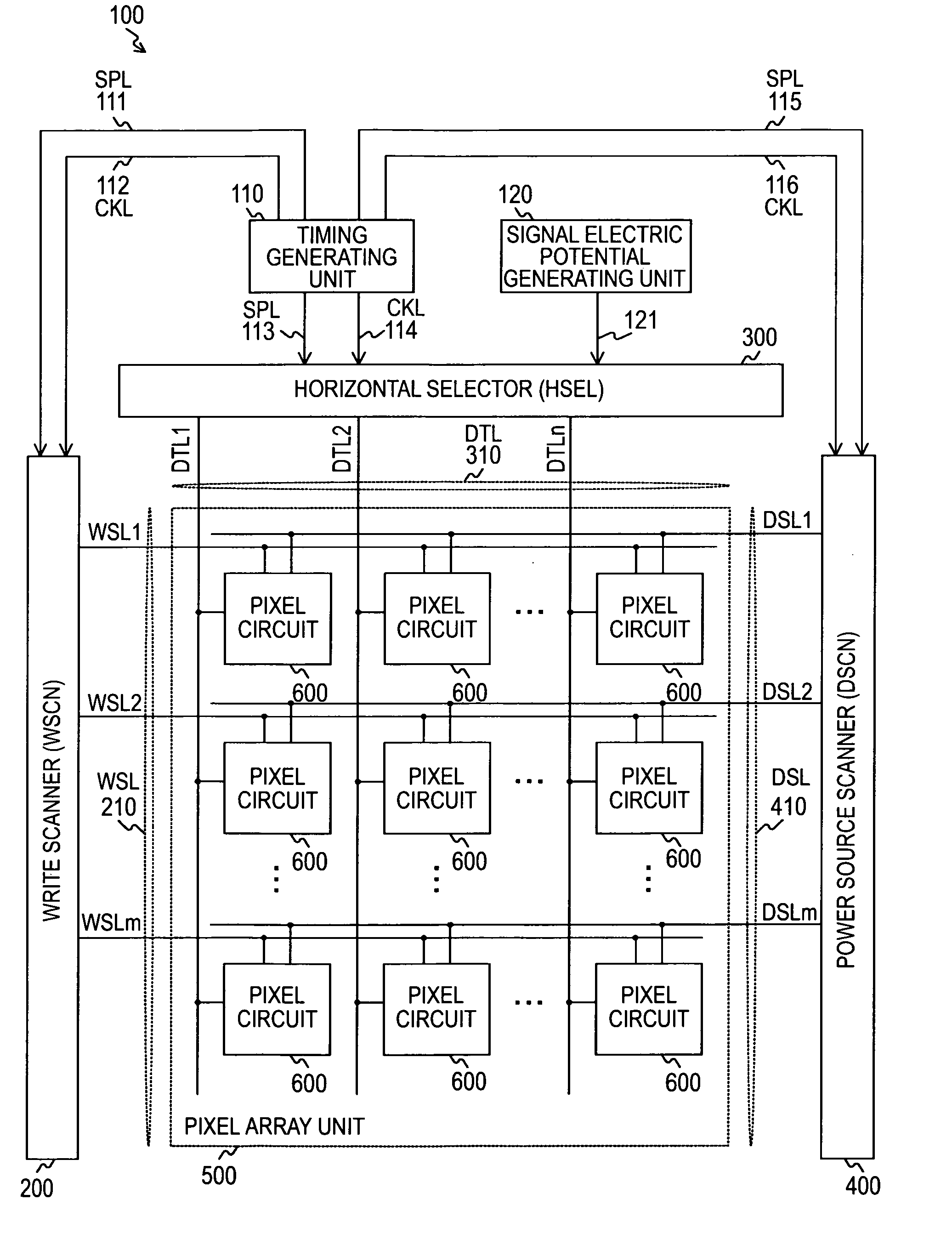
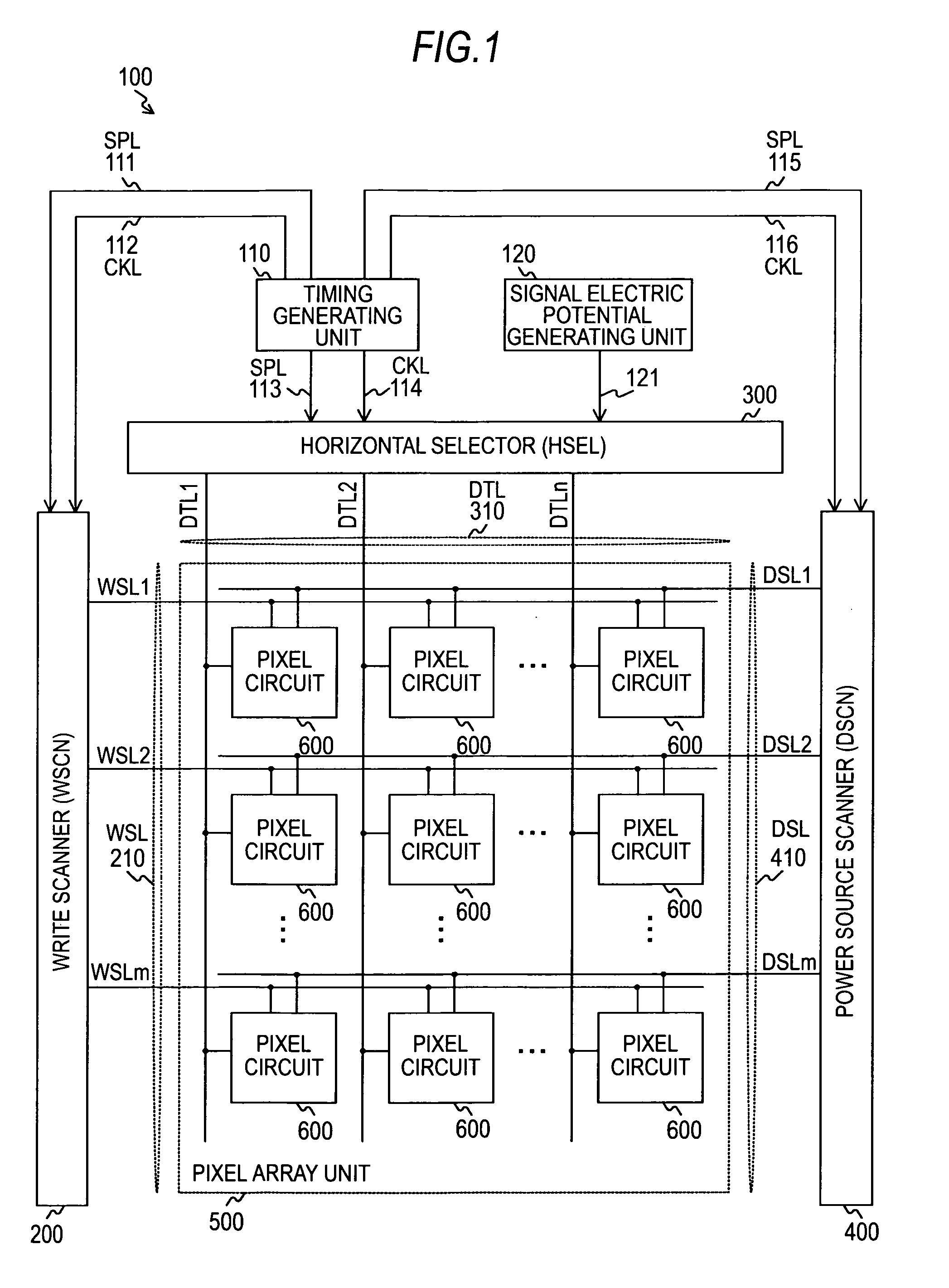
[0007]According to an embodiment of the present invention, there are provided a display device and an electronic apparatus that include: a plurality of pixel circuits; a signal electric potential
generating unit that generates a first signal electric potential, which is used for increasing the number of gray scales of luminance of
light emission of the pixel circuits, and a second signal electric potential, which is equal to or higher than the first signal electric potential, based on a video signal; and a control signal generating unit that generates a control signal used for supplying the first and second signal electric potentials to the pixel circuits. Each of the plurality of the pixel circuits includes a holding
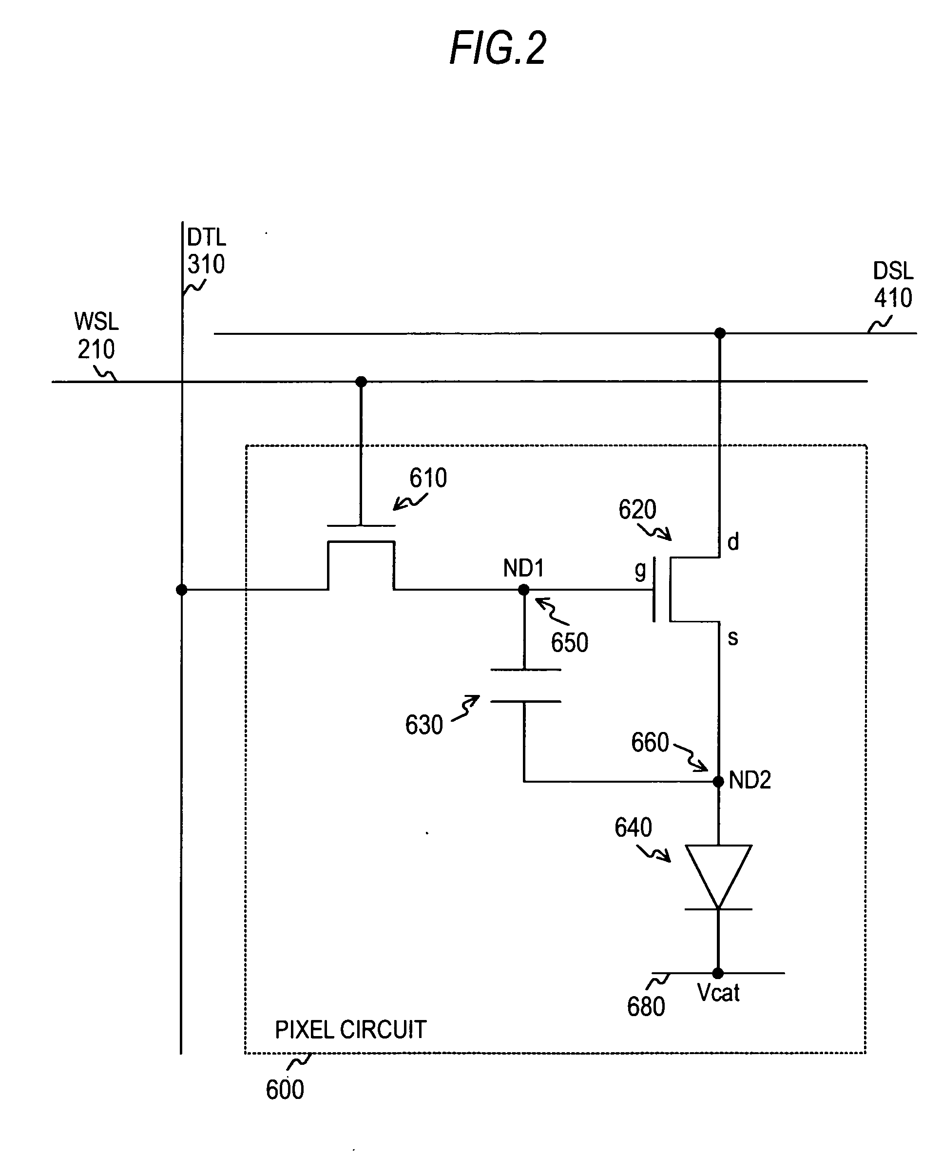
capacitor used for maintaining a signal voltage corresponding to the second signal electric potential, a writing transistor that writes the second signal electric potential to one end of the holding capacitor based on the control signal after writing the first signal electric potential, a driving transistor that outputs a signal current based on the signal voltage corresponding to mobility of the driving transistor at the first signal electric potential written by the writing transistor, and a
light emitting device that emits light in accordance with the signal current output from the driving transistor. Accordingly, an effect of increasing the number of steps of the signal voltage that is maintained in the holding capacitor is acquired by supplying a current corresponding to the mobility of the driving transistor at the first signal electric potential, out of the first and second signal electric potentials generated based on the video signal by the signal electric potential generating unit, to the other end of the holding capacitor.
[0008]In addition, in the above-described embodiment, the signal electric potential generating unit may decrease a step width of the second signal electric potential as the second signal electric potential decreases. In such a case, an effect of decreasing the gray scale interval of the luminance as the luminance level of the pixel circuit decreases is acquired. In the case, it may be configured that the signal electric potential generating unit generates an electric potential used for suppressing supply of the current corresponding to the mobility from the driving transistor to the other end of the holding capacitor in a low signal range in which the second signal electric potential is low as the second signal electric potential, and the driving transistor outputs the signal current based on the signal voltage corresponding to the mobility at the second signal electric potential. In such a case, when the second signal electric potential is within the low signal range, an effect of maintaining the signal voltage in the holding capacitor is acquired by supplying only the current corresponding to the mobility of the driving transistor at the second signal electric potential to the other end of the holding capacitor. In the case, the signal electric potential generating unit may generate an electric potential used for suppressing supply of the current corresponding to the mobility from the driving transistor to the other end of the holding capacitor in the low signal range that is about 1 / 10 of the entire range of the second signal electric potential as the first signal electric potential. In such a case, when the second signal electric potential is within the low signal range that is about 1 / 10 of the entire range of the second signal electric potential, an effect of generating an electric potential for suppressing an increase in the electric potential of the other end of the holding capacitor through mobility correction as the first signal electric potential by using the signal electric potential generating unit is acquired.
[0009]In addition, in the case where the step width of the second signal electric potential is decreased as the second signal electric potential decreases, the signal electric potential generating unit may generate the first and second signal electric potentials that are the same electric potential in the low signal range in which the second signal electric potential is low. In such a case, when the second signal electric potential is within the low signal range, an effect of generating the first signal electric potential that is the same as the second signal electric potential using the signal electric potential generating unit is acquired.
[0011]According to the embodiment of the present invention, a superior
advantage of increasing the number of gray scales of the luminance of a display device without increasing the number of steps of the signal electric potential generated based on a video signal can be acquired.

