Image forming apparatus

a technology of image forming apparatus and forming chamber, which is applied in the direction of electrographic process apparatus, instruments, corona discharge, etc., can solve the problems of increasing the cost of the apparatus and difficulty in adequately correcting the change in image density, and achieves low-cost structure and reduced potential of image bearing members.

Inactive Publication Date: 2011-05-12
CANON KK
View PDF0 Cites 22 Cited by
  • Summary
  • Abstract
  • Description
  • Claims
  • Application Information

AI Technical Summary

Benefits of technology

[0007]A purpose of the invention to provide a feature that a variation in potential of an image bearing member may be reduced in an apparatus having a low-cost structure.

Problems solved by technology

When the density detection sensor and the temperature-humidity sensor are provided in the image forming apparatus, an apparatus cost may increase.
When the density detection sensor and the temperature-humidity sensor are not provided, it is difficult to adequately correct the change in image density.

Method used


Image

  • Image forming apparatus
  • Image forming apparatus
  • Image forming apparatus

Examples


first embodiment

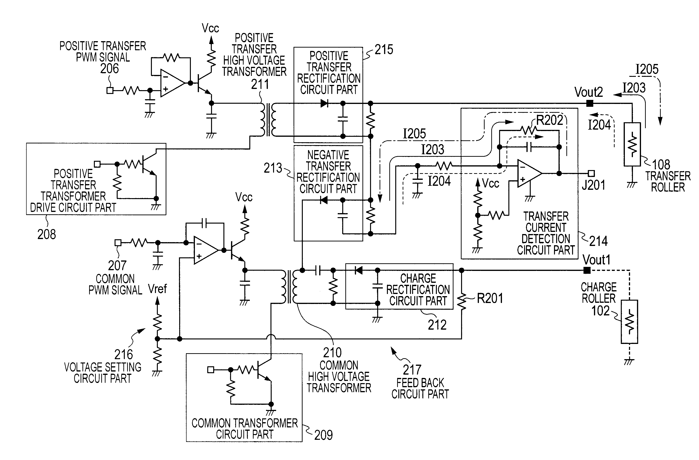
[0046]The common transformer drive circuit part 209 applies, to the charge roller 102, the predetermined charge bias set based on the PWM[1] signal (Step A1610). Processing of Step A1611 to Step A1617 is the same as processing of Step A504 to Step A510 illustrated in FIG. 5 in the first embodiment and thus the description thereof is omitted. Note that, the Δ value used in Step A1613 is any one of the values Δ1, Δ2, and Δ3 set corresponding to the respective circumstances in Step A1608. The CPU 113 determines a bias value for printing (PWM[4]=PWM[2]+ΔPWM) (Step A1618). After the completion of the setting described above, printing starts (Step A1619).

[0047]According to this embodiment, a variation in drum potential due to a variation in resistance value of the transfer roller may be prevented and the variation in drum potential may be suppressed using a low-cost structure without providing a detection part including a density detection sensor or a temperature-humidity sensor.

[0048]Nex...

second embodiment

[0050]FIG. 9 is a flow chart illustrating the control in this embodiment. Processing of Step A1801 to Step A1816 is the same as processing of Step A1601 to Step A1616 illustrated in FIG. 7 in the second embodiment and thus the description thereof is omitted. The CPU 113 determines the bias value (ΔPWM) corresponding to the drum potential which is added to the discharge start voltage (PWM[2]), based on the set value of the positive transfer bias which is obtained in Step A1808 in the case where the constant current control is performed so that the current value flowing into the transfer roller 108 is 2.5 μA. When the set value of the positive transfer bias is larger than the threshold value “A”, the CPU 113 sets “ΔPWM=ΔPWM[1]”. When the set value of the positive transfer bias is equal to or smaller than the threshold value “A” and equal to or larger than the threshold value “B”, the CPU 113 sets “ΔPWM=ΔPWM[2]”. When the set value of the positive transfer bias is smaller than the thre...


PUM


Abstract

The image forming apparatus includes a charging unit, a latent image forming unit, a transfer unit that develops the latent image, a first application unit that applies a voltage to the charging and transfer units, a second application unit that applies a voltage opposite in polarity to the voltage applied from the first application unit, a detection unit that detects a current flowing through the transfer unit, and a control unit that determines whether or not discharge starts between the charging unit and the image bearing member based on the current detected by the detection unit when the voltage is applied from the first application unit to the charging unit. The variation in potential of the image bearing member may be reduced in an apparatus having a low-cost structure without providing a density detection sensor or a temperature-humidity sensor.

Description

BACKGROUND OF THE INVENTION[0001]1. Field of the Invention[0002]The present invention relates to an electrophotographic image forming apparatus including an electrophotographic copy machine, an electrophotographic printer (for example, LED printer or laser beam printer), and an electrophotographic facsimile apparatus.[0003]2. Description of the Related Art[0004]FIG. 10A illustrates a schematic structure illustrating a charge bias circuit of a conventional image forming apparatus. A charge DC bias circuit part (hereinafter, referred to as charge bias application circuit unit) 1201 includes a voltage set circuit part (unit) 1202, a transformer drive circuit part 1203, a high-voltage transformer part (unit) 1204, and a feedback circuit part (unit) 1205. The voltage set circuit part (unit) 1202 may change a voltage value set based on an input PWM signal. The transformer drive circuit part (unit) 1203 drives the high-voltage transformer part (unit) 1204. The feedback circuit part (unit) ...

Claims


Application Information

Patent Timeline
Patent Type & Authority Applications(United States)
IPC IPC(8): G03G15/02G03G15/16
CPCG03G15/1675G03G15/0266
Inventor UEHARA, MASAHIRO
Owner CANON KK
Why Eureka
Try Eureka