
High-efficiency viable sampler for ultrafine bioaerosols

a bioaerosol and sampler technology, applied in the field of bioaerosols, can solve the problems of difficult detection, disease, allergies, respiratory problems, and failure to consider the viability of bioaerosols

Inactive Publication Date: 2011-05-12
UNIV OF FLORIDA RES FOUNDATION INC
View PDF8 Cites 11 Cited by
  • Summary
  • Abstract
  • Description
  • Claims
  • Application Information

AI Technical Summary

Benefits of technology

The present patent describes a system for detecting bioaerosols, which can be used to detect the presence of living organisms in the air. The system includes a humidifier that binds to the bioaerosols, an amplifier that increases the size of the bioaerosols, and heat pumps to control the temperature between the humidifier and the amplifier. The system can also include additional components such as a biocompatible impinger, a biocompatible impactor, a biocompatible cyclone separator, or a biocompatible electrostatic precipitator to collect the amplified bioaerosols. The technical effect of this system is that it provides a reliable and sensitive method for detecting bioaerosols in the air, which can be useful in various applications such as in the field of air quality monitoring or in the detection of bioterrorism agents.

Problems solved by technology

Bioaerosols typically occur in very low concentrations making them very hard to detect.
Airborne microorganisms or bioaerosols can cause disease, allergies, and respiratory problems.
However, most of them are for inert aerosols and their designs do not consider the viability of bioaerosols.
Furthermore, they are not capable of distinguishing biological agents from inert agents in the same sample volume.
Such a method of detecting and identifying a bioaerosol is rather complex, relying on relatively expensive and complex equipment.
Furthermore, the method has not been demonstrated to be able to accurately identify speciation and quantify viable concentration in practical applications.
Unfortunately, this approach dries out agar quickly and therefore cannot be used for collecting viable bioaerosols.
Existing viable impactors such as the Anderson Impactor can only collect down to 0.6 μm due to this limitation.
As described, either a viable impactor or an impinger has low efficiency for bioaerosols below 0.3 μm.

Method used


Image

  • High-efficiency viable sampler for ultrafine bioaerosols
  • High-efficiency viable sampler for ultrafine bioaerosols
  • High-efficiency viable sampler for ultrafine bioaerosols

Examples


example

Detection and Sampling of MS2 Type Bacteria

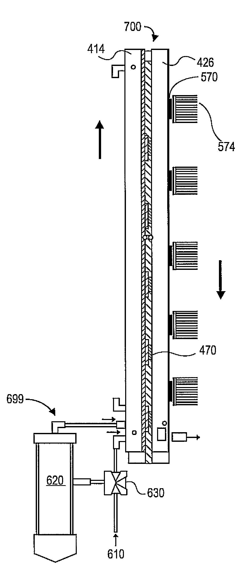
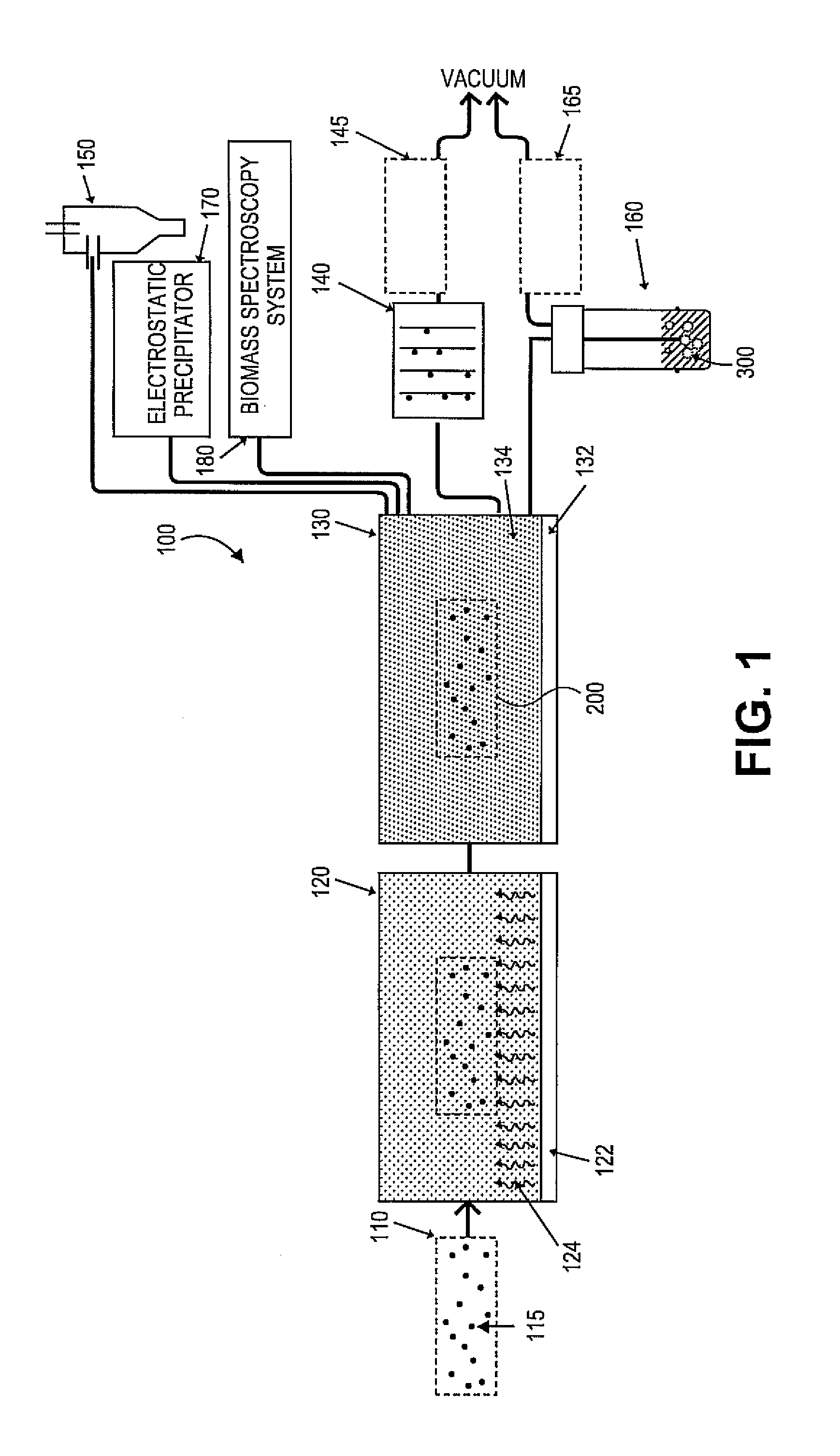
[0069]A bioaerosol generation system was connected to an assembled bioaerosol detection system (e.g., see FIG. 1 and FIGS. 4A-4B) having Six 8 W Peltier junctions for an inline analysis of capture efficiency. MS2 type bacteria phages were chosen as the test sample because of their representative size for the most challenging viral aerosols (28 nm). Baseline tests were performed with the aerosol detection device connected but being turned off in order to obtain an accurate account for the effects of the aerosol size amplification. Humidity at the exit of the heating tube was measured to ensure an ultimate humidity of at least 90% (relative). Four temperatures at the beginning and ends of both the tubes were measured.

[0070]Results from the experiments were collected and are displayed in Table 1. As shown in Experiment I, for the baseline (see set 1 or 5) with the size amplification system turned off, the concentration of MS2 was on average of...


PUM

PropertyMeasurementUnit
diameteraaaaaaaaaa
temperatureaaaaaaaaaa
diameteraaaaaaaaaa

Abstract

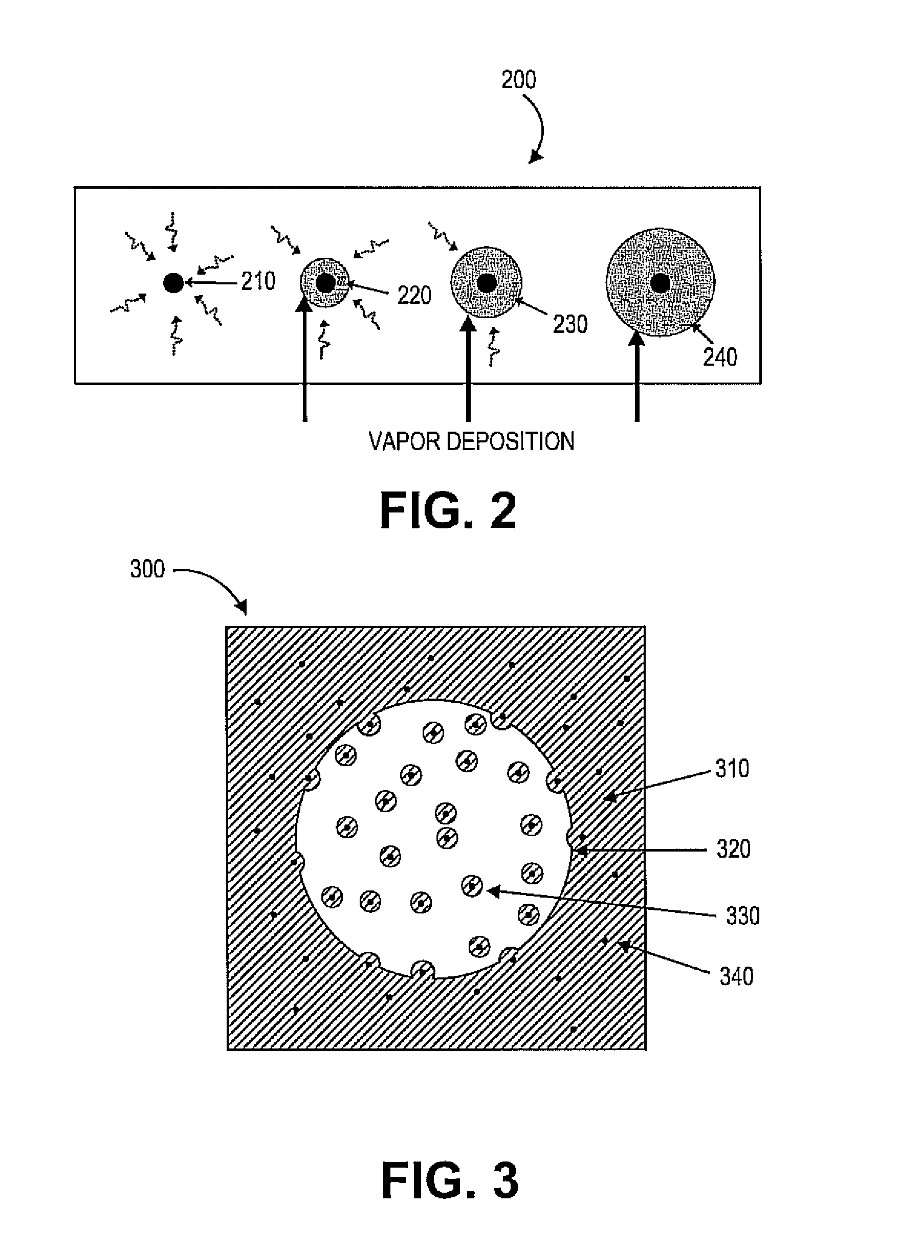
Exemplary embodiments provide bioaerosol detection systems and methods for detecting bioaerosols. In one embodiment, the bioaerosol detection system can include a humidifier to increase the humidity of a continuously flowing sample volume of a bioaerosol sample using a biologically compatible liquid medium, and an amplifier to deposit vapor on the bioaerosol sample for a particle size amplification process. Bioaerosol(s) can thus be detected and sampled while simultaneously maintaining their viability. The disclosed bioaerosol detection systems and the methods can provide high efficiency for sampling and detecting ultrafine bioaerosol(s) such as viruses and proteins, which can be smaller than 0.3 μm in diameter and can be as small as 20 nm.

Description

RELATED APPLICATIONS[0001]This application claims priority to U.S. Provisional Patent Application No. 60 / 956,316, filed Aug. 16, 2007, and is a national phase application of PCT / US20081073267 filed on Aug. 15, 2008, the disclosure of which is incorporated by reference herein in its entirety.GOVERNMENT RIGHTS[0002]This invention was made with government support under Contract No. FA8650-06-005913 awarded by the United States Air Force (USAF). The government may have certain rights in the invention.FIELD OF THE INVENTION[0003]This invention relates generally to bioaerosols and, more particularly, to a system for detecting bioaerosols.BACKGROUND OF THE INVENTION[0004]Bioaerosols typically occur in very low concentrations making them very hard to detect. Bioaerosols can be found in the workplace, in residences, in medical facilities, in manufacturing operations, in animal processing facilities, in dairy facilities or other animal houses, in recycling or composting plants, in sanitary la...

Claims


Application Information

Patent Timeline
Patent Type & Authority Applications(United States)
IPC IPC(8): C12Q1/70C12M1/34
CPCG01N1/2202G01N15/06G01N15/0625G01N2015/0693G01N2001/2223G01N2015/0261G01N15/065G01N15/075
Inventor WU, CHANG-YUTHEODORE, ALEXANDROS DEMETRIOSLEE, JIN-HWAREIMENSCHNEIDER, LINDSEY ANN
Owner UNIV OF FLORIDA RES FOUNDATION INC
Learn More