Measurement device and measurement method

a measurement device and measurement method technology, applied in the field of measurement devices and measurement methods, can solve the problems of large load on the moving organism, lack of esri images when handling internal organs,

Inactive Publication Date: 2011-05-12
FUJI ELECTRIC CO LTD +1
View PDF6 Cites 10 Cited by
  • Summary
  • Abstract
  • Description
  • Claims
  • Application Information

AI Technical Summary

Benefits of technology

Moreover, the measurement method of the present invention is characterized in that it includes causing a measurement subject to pass in sequence through the magnetic fields of a first magnetic field generation device that generates a magnetic field of a set size and a second magnetic field generation device that generates a magnetic field of a size that differs from that of the magnetic field of the first magnetic field generation device by causing the measurement subject or the first and second magnetic field generation devices to move rotationally, and measuring images of the measurement subject in different magnetic fields without stopping the measurement subject or the first and second magnetic field generation devices while it is (they are) being moved rotationally by said rotational movement device.
With these inventions, it is possible to obtain images such as functional images, histological images, etc. of the measurement subject by causing magnetic fields of differing sizes to be generated by multiple magnetic field generation devices, causing the measurement subject or the first and second magnetic field generation devices to move rotationally, and using various types of magnetic resonances such as electron spin resonance, nuclear magnetic resonance, etc. while causing the measurement subject to pass through the magnetic fields of these multiple magnetic field generation devices sequentially.
Either one of the first or the second magnetic field generation device may generate the larger magnetic field, but if the second magnetic field generation device generates a magnetic field larger than the magnetic field generated by the first magnetic field generation device, it is possible to use the first magnetic field generation device, with a lower magnetic field, as an OMRI electron spin excitation device, and the second magnetic field generation device, with a higher magnetic field, as an MRI and OMRI external magnetic field generation device. By doing this, MRI images and OMRI images can be obtained from the second magnetic field generation device. Specifically, with this measurement device, since OMRI measurement is performed using the second magnetic field generation device, with a high magnetic field, after electron spin is excited by the first magnetic field generation device, with a low magnetic field, the OMRI external magnetic field becomes extremely large, and it is possible to obtain high-sensitivity, high-resolution OMRI images.
Thus, since the measuring device of the present embodiment is intended to perform measurement through the first and second magnetic field generation devices exciting magnetic resonance, it is possible to obtain images such as functional images, structural images, etc. of the measurement subject by using various types of magnetic resonances, such as electron spin resonance, nuclear magnetic resonance, etc.
(1) Since the structure is such that the measurement subject is made to pass through the magnetic fields of the first and second magnetic field generation devices sequentially, and images of the measurement subject are measured in different magnetic fields without stopping the measurement subject or the first and second magnetic field generation devices, there is no need to cause the measurement subject to move repetitively, and it is possible to obtain functional and structural images of the measurement subject by using various types of magnetic resonances such as electron spin resonance, nuclear magnetic resonance, etc. while causing the measurement subject or the first and second magnetic field generation devices to move rotationally without stopping, therefore, there being no stopping for measurement as with conventional devices, it is possible to eliminate the load generated by stopping. Moreover, there is also no load imposed on the first and second magnetic field generation devices by stopping.

Problems solved by technology

However, ESRI images are lacking when it comes to handling internal organs.
Thus, there is the problem that a large load is imposed on the moving organism to be measured by this biometric device.

Method used


Image

  • Measurement device and measurement method
  • Measurement device and measurement method
  • Measurement device and measurement method

Examples


second embodiment

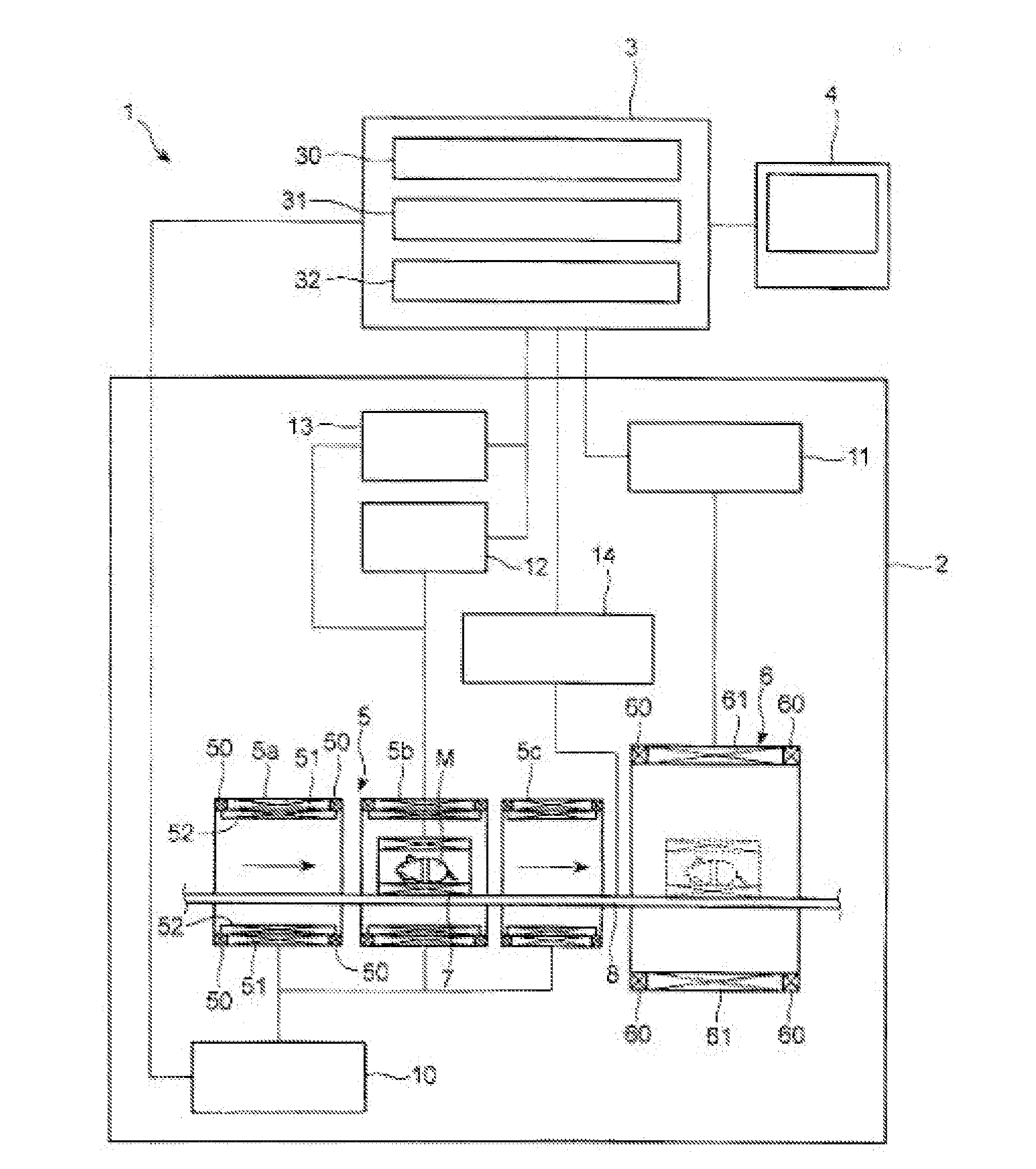
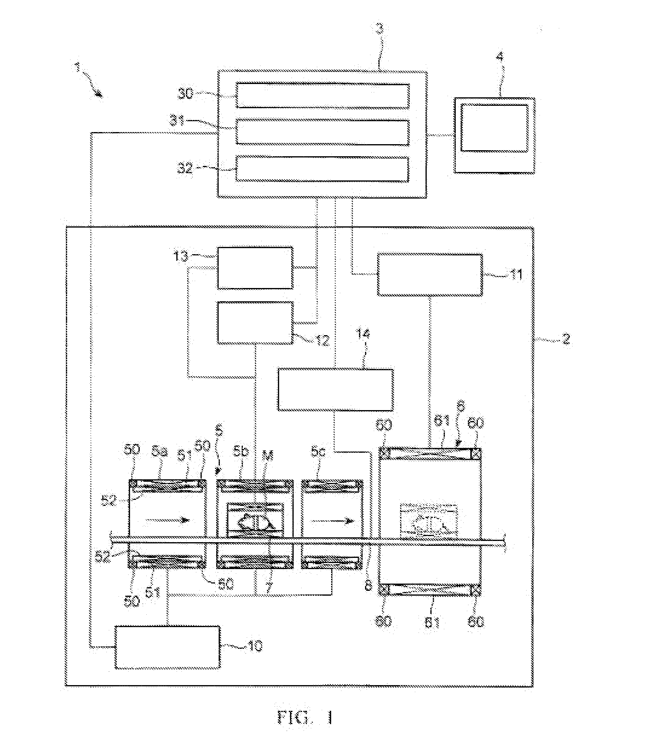
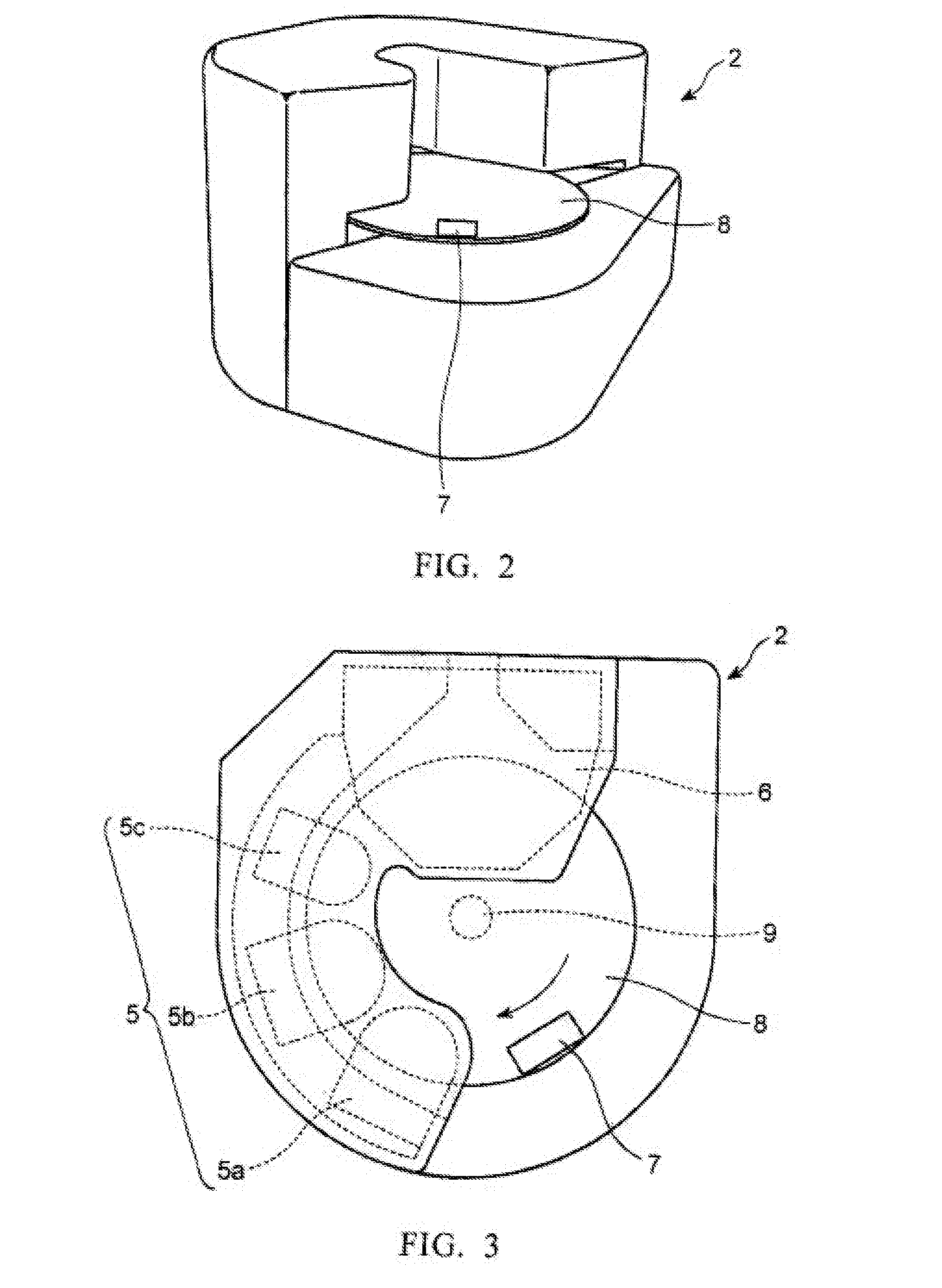
FIG. 4A is a perspective view of an exemplary embodiment of a measurement system 100 according to the present invention. FIG. 4B is a plan view of the measurement system 100 illustrated in FIG. 4A. Measurement system 100 includes a first imaging assembly (external magnetic field generation devices 5 and 6) 70, a second imaging assembly (x-ray machine 40), cylinder RF coils 7a and 7b and rotating table 8 rotated by rotational drive mechanism 9. As illustrated, RF coil 7a is fixed on the periphery of rotating table 8 to the left of x-ray machine 40 and RF coil 7b is fixed on the periphery of rotating table 8 to the right of external magnetic field generation device 5a. The RF coils 7a and 7b are configured to accommodate measurement objects M1 and M2, respectively, having a diameter preferably of 1 cm to 7 cm for small animals and objects having a diameter of 20 cm to 40 cm for human body parts, for example.

As illustrated in FIG. 9 which is discussed in greater detail below, RF coil 7...

first embodiment

First imaging assembly (external magnetic field generation devices 5 and 6) 70 operates in substantially a similar manner discussed above with the present invention except for the measurement object is stopped while being measured as it moves through the external magnetic field generation devices 5 and 6. This is because the first imaging assembly is provided in combination with an imaging assembly (x-ray machine 40) that requires the measurement object to remain still while being imaged. The x-ray machine 40 operates by observing the absorption of radiation on the measurement object M. According, the x-ray machine 40 includes a control device 42, a radiation device 41 and a housing 43 to support the control device 42 and the radiation device 41. Control device 42 communicates with control part 3a to operate the x-ray machine 40 and to process the image to be shown on display part 4. According to an alternative embodiment of the present invention, x-ray machine 40 may only include t...


PUM


Abstract

A measurement device and measurement method make it possible to eliminate the load generated by stopping on a measurement subject that is moved among multiple magnetic field generating devices. The measurement device includes a first external magnetic field generating device that generates a magnetic field of a set size, a second external magnetic field generating device that generates a magnetic field of a size that differs from that of the magnetic field of the first external magnetic field generating device, a rotating table that causes the subject of measurement to pass in sequence through the magnetic fields of the first and second external magnetic field generating devices by causing the subject of measurement to move rotationally, and an OMRI measurement processing part and MRI measurement processing part that measures images such as functional images or structural images of the subject of measurement while it is being moved rotationally by the rotating table.

Description

BACKGROUND OF THE INVENTION1. Field of the InventionThe present invention relates to measurement devices and measurement methods for obtaining images, such as functional images, structural images, etc., for a measurement subject using various types of magnetic resonances, such as an electron spin resonance (ESR), nuclear magnetic resonance (NMR), etc.2. Description of the Related ArtRedox metabolism, including active oxygen and free radicals, is closely involved in many physiological phenomena and disease components and progress. Thus, if it is possible to make redox dynamics visible at the individual level, in small experimental animals, there is no doubt that this would greatly contribute to the clarification of vital phenomena, the analysis of disease, the establishment of therapeutic methods for such diseases, and the development of drugs.Electron spin resonance imaging (ESRI), which specifically detects free radicals, which are intermediate products of redox metabolism, is effe...

Claims


Application Information

Patent Timeline
Patent Type & Authority Applications(United States)
IPC IPC(8): A61B5/055
CPCA61B5/0555G01N24/10G01R33/3806G01R33/381G01R33/3815G01R33/383A61B2503/40G01R33/4812G01R33/56375G01R33/56383G01R33/60G01R33/62G01R33/481A61B5/0035A61B5/055
Inventor ICHIKAWA, KAZUHIROUTSUMI, HIDEO
Owner FUJI ELECTRIC CO LTD
Why Eureka
Try Eureka