Expandable cerebrovascular sheath and method of use

a cerebrovascular and expandable technology, applied in the field of medical devices, can solve the problems of inability to negotiate into, or far from the guide catheter, and insufficient advancement of the guide catheter, etc., and achieve the effect of convenient removal of the sheath from the patient, high strength of the sheath, and control of cross-sectional shap

Inactive Publication Date: 2011-05-12
ONSET MEDICAL CORP
View PDF7 Cites 109 Cited by
  • Summary
  • Abstract
  • Description
  • Claims
  • Application Information

AI Technical Summary

Benefits of technology

[0010]The expandable sheath can be used to assist with cerebrovascular access procedures in that it allows for a small diameter, highly flexible, access to the cerebrovasculature in its first, smaller cross-sectional state. Following advancement to a target location within the neurovasculature or cerebrovasculature, the collapsible region of the sheath or guide catheter can be diametrically expanded such that it retains a substantially uniform cross-sectional lumen from its proximal end to its distal end. In its enlarged state, with the collapsible distal region having been fully dilated, the guide catheter can serve as a pathway large enough in size for introduction of large interventional, therapeutic, or diagnostic devices therethrough. Interventional neuroradiologists (INR) generally prefer to perform interventional procedures where the access is percutaneous and does not require a surgical cutdown. The expandable cerebrovascular guide catheter or access sheath can reduce procedure time, decrease procedure cost, reduce trauma to the patient, and improve patient outcomes by advancing further into the cerebrovasculature toward a target lesion than would have been otherwise possible with a non-expandable sheath or guide catheter. This extra advancement reduces the risk of distal embolization or vessel wall damage and increases the ability to route instrumentation to the target region.
[0012]In other arrangements, the distal end of the sheath can comprise a flared component that becomes larger in diameter moving distally. The flared component can comprise a taper, or it can comprise a taper and a region of relatively constant diameter affixed or integral to the tapered region at its most distal end. The flared component can be integral to the distal end of the expandable portion of the sheath, or it can be affixed thereto. The flared component can be expanded using a balloon dilator, it can be expanded using self-expansion modalities, or it can comprise self-expansion with balloon dilator assist. The self-expansion can be due to resilient spring forces, or due to shape memory forces generated by sheath reinforcement components fabricated from nitinol, or other shape memory materials. The flared configuration can facilitate re-capture or removal of instruments, embolic material, debris, or implantable devices such as percutaneously delivered aortic heart valves. The expandable, flared region of the sheath can range in length between 1-cm and 10-cm, with a preferred range of 2-cm to 5-cm. In an embodiment, the flared region can use the same balloon as the rest of the distal expandable region for expansion, or it can be expanded by a separate balloon.
[0022]The reinforcement of the expandable regions can comprise wire, preferably malleable wire. The wire can have a round cross-section, a rectangular cross-section, a ribbon-like cross-section, or the like. The malleable wire can be bent by a dilator balloon, tapered dilator, hollow dilator, or the like, into the second, larger cross-section and the strength of the malleable wire can substantially overcome any resilient spring-back imparted by the polymeric component of the sheath wall.
[0028]In certain embodiments of the sheath wall construction, an inner layer of polymer and an outer layer of polymer sandwich a reinforcing layer. The reinforcing layer can be a coil of metal such as, but not limited to, titanium, stainless steel, cobalt nickel alloy, nitinol, tantalum, and the like. The coil is preferably malleable, with little or no spring properties, and does not exhibit any elastomeric tendencies. The coil can be fabricated from flat wire with a thickness of 0.0005 to 0.010 inches and preferably 0.0007 to 0.005 inches. The width of the flat wire can range from about 0.003 to 0.050 inches and preferably from about 0.005 to 0.010 inches. The spacing between the coils can, for example range from substantially 0 to approximately 5 times the width of the coil wire, with an exemplary spacing equal to about the width of the coil wire. The coils can be fabricated from round stock, flat stock, or the like. The reinforcement can be sandwiched between the inner layer and the outer layer of polymeric material, wherein the inner and outer layers can be bonded or welded to each other through the space between the coils. The inner and outer polymeric layers can be fabricated from the same or different materials. Suitable materials for the inner and outer layers include, but are not limited to, polyurethane, silicone, Hytrel, PEEK, polyethylene, HDPE, LDPE, polyester (e.g. PET), polyethylene blends, and the like. In yet another embodiment, a plastically deformable, malleable, or annealed, braid structure can also be used for reinforcement to beneficially eliminate the need for the malleable coil and permit a reduction in wall thickness while retaining the tensile strength and torqueability of the braid. In yet other embodiments, the reinforcement can comprise a stent-like structure.
[0029]In certain embodiments, the guide catheter sheath shaft can comprise multiple regions of varying flexibility along the axial length of the shaft. In some embodiments, the guide catheter dilator shaft can have at least two regions of different flexibility. In other embodiments, the guide catheter shaft can comprise three or more (with a practical upper limit of six) regions of different flexibility. In yet other embodiments, the sheath shaft flexibility can be reduced toward the proximal end of the guide catheter and increased moving toward the distal end of the guide catheter. Moving from the proximal to the distal end of the guide catheter shaft, the flexibility of a given discreet section can be greater than the flexibility of the region just proximal and adjacent to said discreet section. A guide catheter sheath having a substantially collapsed, small diameter distal region can exhibit significantly increased flexibility in that area over its flexibility in non-expandable, or fully expanded, expandable regions. Such flexibility is especially useful when traversing tortuous or curved anatomy such as the aortic arch into the brachiocephalic trunk (innominate arteries). Following such traverse, the guide catheter sheath can be expanded to create a stiffer, larger diameter structure.
[0033]The main reasons for the malleable embodiments include control over cross-sectional shape, ability to embed the reinforcement in the polymer layers without needing to create some difficult-to-manufacture decoupling of the polymer and the reinforcement, the high strength of the sheath following placement, and prevention of lumen re-collapse caused by body tissue. The ability of this device to remodel to the desired shape to generate a superhighway for placement of implants and other medical devices is superior to anything available today. Furthermore, the device provides a relatively smooth interior lumen, which allows passage of instruments and implants of very large size without excessive binding or friction. No other sheath exists today that has these benefits. The malleable reinforcements embedded within the sheath are configured to generate sufficient force that they control and maintain the diameter of the radially collapsed, unexpanded sheath. The malleable reinforcements are further configured to maintain the sheath in its open, radially expanded configuration, following dilation with a balloon or other dilator, residing within the sheath lumen. The structure of the malleable metal reinforcement is sufficient to overcome, or dominate, any resilient or structural forces exerted by the polymeric components of the sheath tubing, which generally surround, or encase, the reinforcement. The structure of the malleable metal reinforcement also is sufficient to overcome any inwardly biased forces imposed by any tissue through which the sheath is inserted, such as, for example, muscle mass and fascia lying between the skin and the femoral or iliac arteries, or stenotic arterial buildup including thrombus or atherosclerotic plaque.

Problems solved by technology

Adequate advancement of guide catheters is generally restricted by the tortuous anatomy of the carotid or vertebral arteries, as well as their small size.
Guide catheters are generally unable to negotiate into, or far into, the circle of Willis due to the tortuous anatomy leading thereto.

Method used


Image

  • Expandable cerebrovascular sheath and method of use
  • Expandable cerebrovascular sheath and method of use
  • Expandable cerebrovascular sheath and method of use

Examples


Embodiment Construction

[0061]As used herein, the terms proximal and distal refer to directions or positions along a longitudinal axis of a catheter or medical instrument. Proximal refers to the end of the catheter or medical instrument closest to the operator, while distal refers to the end of the catheter or medical instrument closest to the patient. For example, a first point is proximal to a second point if it is closer to the operator end of the catheter or medical instrument than the second point. However, the terms anatomically proximal and anatomically distal refer to orientations within the body. A point is more anatomically distal if it is further from the heart than a point described as anatomically proximal.

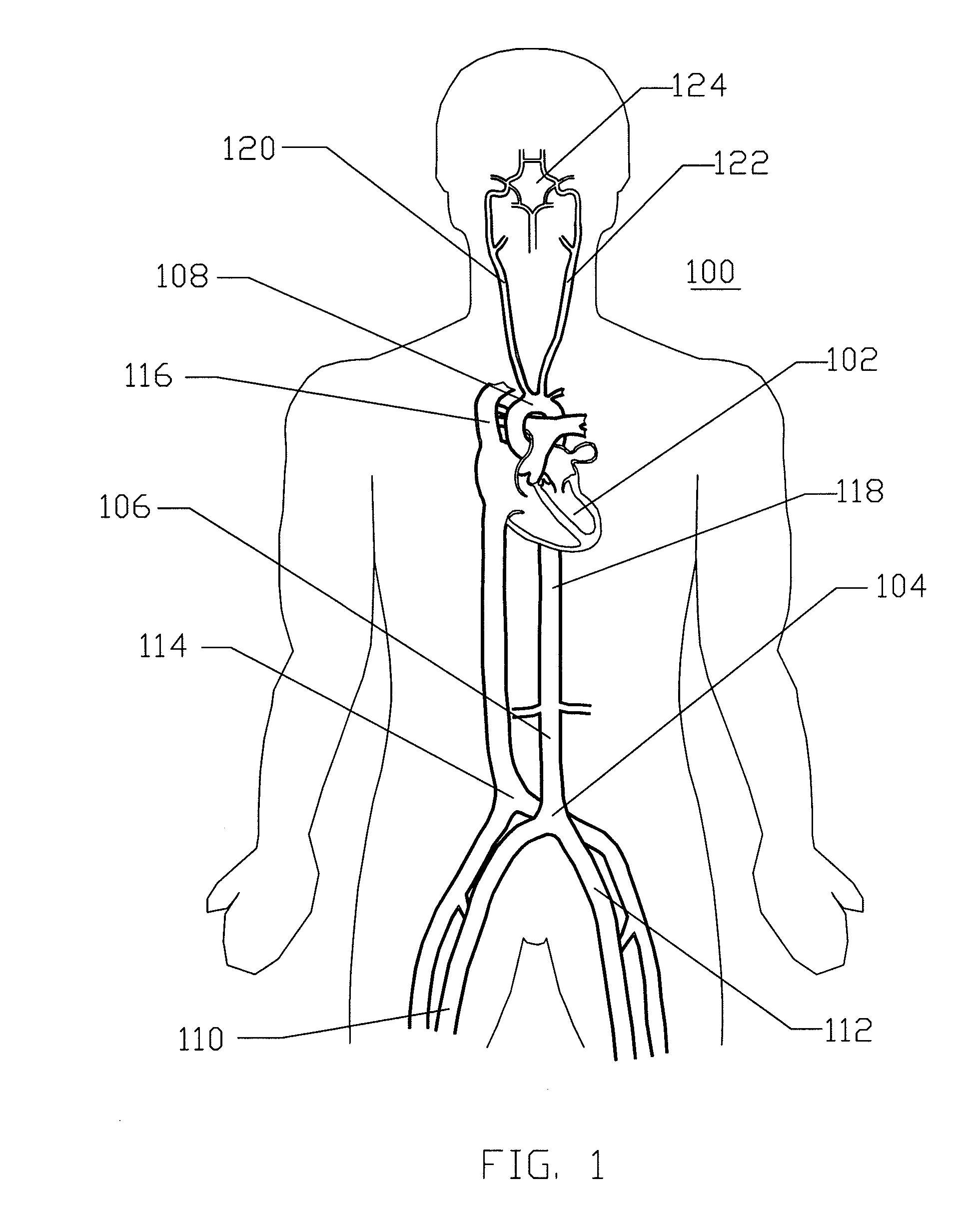
[0062]FIG. 1 is a schematic frontal (anterior) illustration (looking posteriorly) of a human patient 100 that illustrates components of the central circulation. As shown, the central circulation generally comprises a heart 102, an aortic bifurcation 104, a descending aorta 106, an aortic arc...


PUM


Abstract

Disclosed is an expandable transluminal sheath, for introduction into the body while in a first, small cross-sectional area configuration, and subsequent expansion of at least a part of the distal end of the sheath to a second, enlarged cross-sectional configuration. The sheath is configured for use in the upper vascular system and has utility in the introduction and removal of therapeutic or diagnostic microcatheters. The access route is through the femoral arteries or the iliac arteries to the cerebrovasculature. The distal end of the sheath is maintained in the first, low cross-sectional configuration during advancement to the cerebrovasculature. The distal end of the sheath is subsequently expanded using a radial dilatation device, which is removed prior to the introduction of microcatheters. The sheath can be inserted in a first, small cross-sectional configuration, be expanded diametrically to a second, larger cross-sectional configuration, and then be reduced to a diametrically smaller size for removal.

Description

PRIORITY CLAIM[0001]This application claims priority under 35 U.S.C. §119(e) to U.S. Provisional Application No. 61,241,740 filed on Sep. 11, 2009, the entire contents of which are hereby incorporated by reference herein.BACKGROUND OF THE INVENTION[0002]1. Field of the Invention[0003]The present invention relates to medical devices for percutaneously accessing the cardiovascular system and, more specifically, accessing the cerebrovasculature.[0004]2. Description of the Related Art[0005]A wide variety of diagnostic or therapeutic procedures involve the introduction of a device into the vasculature through a percutaneous or open surgical incision at an access site and then routing the device to a remote location within the body for therapy or diagnosis at the remote location. Such remote locations within the body include the neurovasculature or cerebrovasculature. Catheters are routed to the cerebrovasculature over guidewires, through guide catheters, or both. A percutaneous technique...

Claims


Application Information

Patent Timeline
Patent Type & Authority Applications(United States)
IPC IPC(8): A61M29/02A61F2/958
CPCA61M25/0023A61M25/005A61M25/01A61M25/1011A61M2025/1084A61M2025/0024A61M2025/0042A61M2025/0681A61M2025/1052A61M29/02
Inventor LENKER, JAYBISHOP, JOSEPHJONES, MARK T.NGUYEN, HUAN T.
Owner ONSET MEDICAL CORP
Why Eureka
Try Eureka