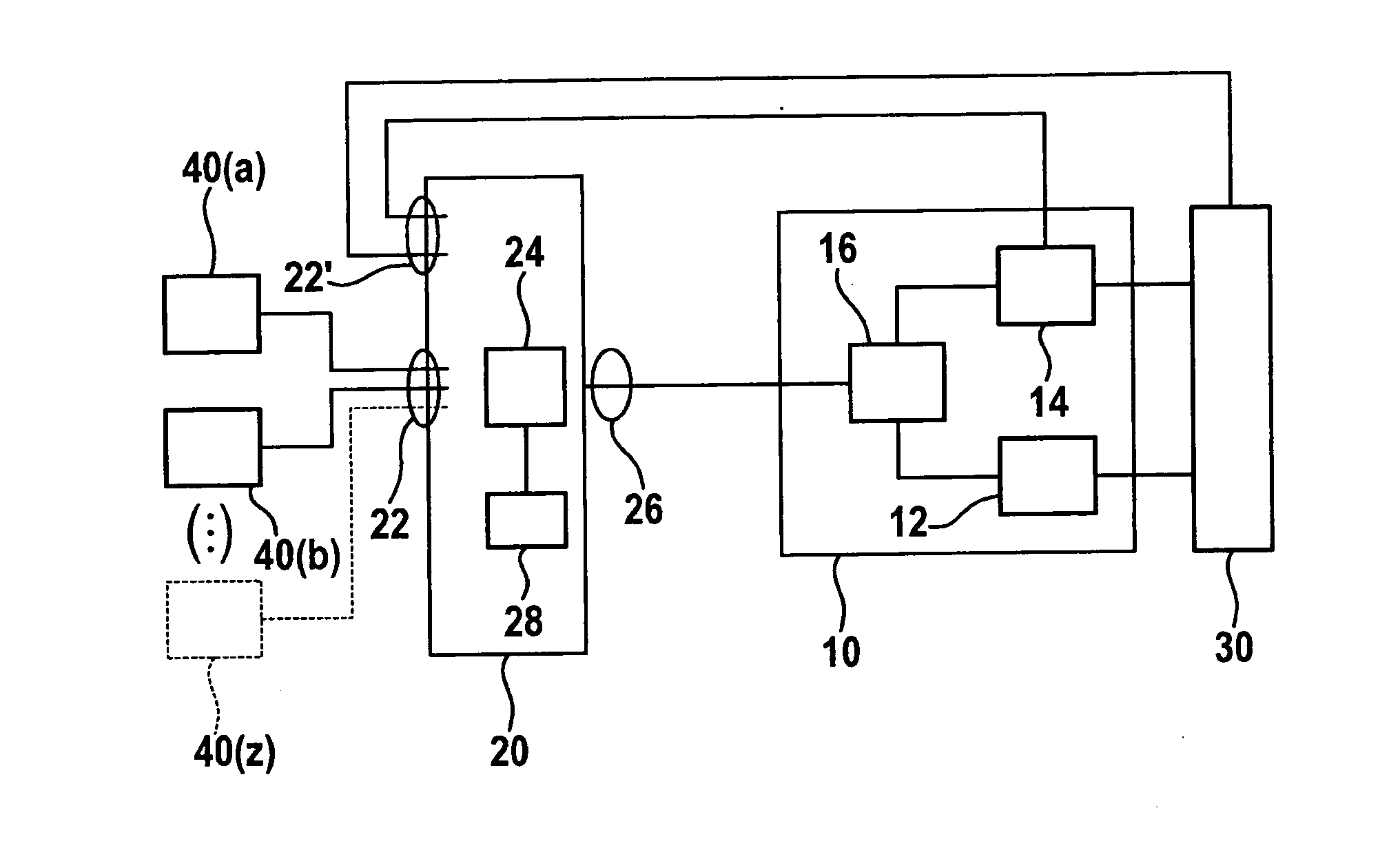
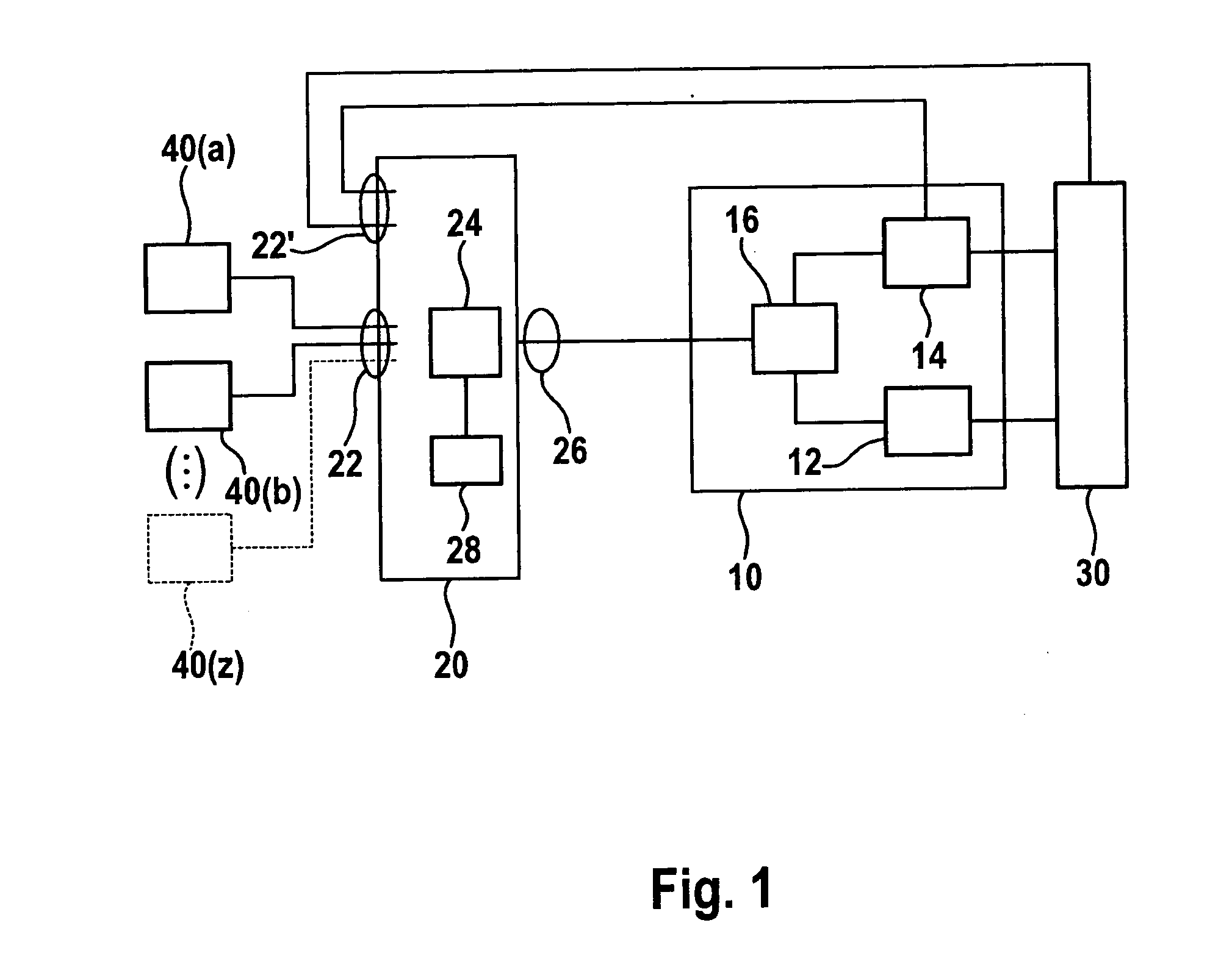
[0009]The present invention allows automatic result-based switching of the drive mode and prevents changes in drive mode which would result in an unwanted driving performance. At the same time the efficiency of the drive is not substantially impaired. The significance of the method according to the present invention in evaluating the driving performance may be illustrated on the basis of the following example. If a heavily loaded P2
hybrid vehicle, for example, is driving on a steep ramp (for example, a garage entrance) at the highest
gear ratio, using the electric motor exclusively, then a brief attempt to accelerate would massively impair the driving performance as described below. If the driver attempts to accelerate by depressing the accelerator pedal, the torque of the electrical
machine is sufficient only for a slight acceleration but is not sufficient to additionally start the internal combustion engine, then the vehicle would open the
clutch on the transmission end to start the internal combustion engine to thereby support the total drive torque with the additional drive torque of the internal combustion engine. Opening the clutch or merely using the electric motor as a
starter would result in a jerky movement and in the worst case could even have the unwanted result of the vehicle rolling in reverse. In the same way, shutdown of the internal combustion engine, for example, due to a low driving speed would suddenly reduce the total driving power so that the vehicle would roll back.
[0010]However, according to the present invention, a jerky movement and rolling in reverse in particular are easily prevented by detecting the result based on the intensity of the potential jerky movement by determining a torque shortfall to estimate on the basis of the shortfall whether a change in operating mode would result in an excessive movement or a jerky movement which would still be tolerable. The method according to the present invention is capable of preventing a jerky movement caused not only by turning on the internal combustion engine but also by turning off the internal combustion engine. For example, a control may find that with a combined electric motor / internal combustion engine operation, the desired acceleration (cf. gas pedal position) is achievable even when the internal combustion engine is turned off. However, that is not the case with heavily loaded vehicles because according to the related art, the decision about shutting down the internal combustion engine is not made on the basis of the load state, i.e., the load, but according to the present invention the required drive performance and / or the required driving torque is / are ascertained by taking into account the load. Therefore, the desired driving performance at an elevated load, i.e., a high gradient and / or
heavy load, for example, is taken into account. The present invention is preferably used in particular for at least temporarily preventing an internal combustion engine from stopping in the appropriately detected situations.
[0011]According to the present invention, a drive mode change
signal is thus detected; this signal may originate from an operating switch or from a higher-level drive control. The drive mode change signal corresponds to the intent of the controller to induce a change in drive mode and thus characterizes a change in drive mode, which is planned and / or desired by the driver (or by the vehicle controller). Instead of implementing the change in drive mode directly and absolutely, as done in the related art, according to the present invention a torque shortfall, which would occur due to the change in drive mode, is first determined or estimated. According to the present invention, the torque shortfall is compared with a threshold value, the threshold value indicating the tolerance threshold of the driver and thus the desired driving performance. At a very high threshold value, which would occur only with a very great drop in drive torque or with very marked jerky movements, i.e., with a very
high torque shortfall, the drive would still operate efficiently, but the driving
sensation would be greatly impaired. At a very low threshold level, however, an increase in efficiency may be foregone in favor of an improved driving performance. The height of the threshold value is thus a measure of the quality of the driving performance or efficiency, so that driving performance and efficiency require opposing measures and thus a compromise decision must be made. In preventing the stoppage of an internal combustion engine in particular, this yields a protection against
rollback, for example, at (high) threshold values.
[0012]According to the present invention, instead of immediately executing the change in drive mode when a drive mode change signal occurs, the change in drive mode is blocked when the torque shortfall is above the threshold value. Otherwise if the threshold value is not exceeded or if the torque shortfall is below the threshold value, the drive mode change signal is relayed to the corresponding control of the
hybrid drive in order to execute the corresponding change in drive mode. Furthermore, a change in drive mode is effectively prevented, i.e., blocked only for a predetermined interval of time, for example, when starting of the internal combustion engine is desired.
[0016]The
load torque is used for “modeling” and is used to provide the increase in drive torque supplied by the
hybrid drive as required for the change in speed, for example, to reduce or completely compensate for the torque shortfall. In particular, a gradient of the roadway, a load (weight) of the vehicle, or a combination thereof is provided and used for this purpose. The
load torque may be a variable, which corresponds to a torque required for providing the change in speed or for maintaining a speed.
[0019]If the drive mode change signal characterizes the second transition, i.e., the transition from combination operation to only-electric motor operation, then the drive torque shortfall corresponds to the torque, which is contributed by the internal combustion engine to the drive before the change, and which is no longer available after shutdown of the internal combustion engine. In particular applying this method to the second transition results in a great improvement in
driving safety because it prevents a jerky movement and / or rolling in reverse, which would occur due to a sudden reduction in torque (as a result of stopping the internal combustion engine despite inadequate power of the electric motor). If necessary, in addition to the failure of torque production by the electric motor, additional clutch friction effects are also to be taken into account as torque shortfall in the advance calculation / ascertainment of the expected torque shortfall. As already noted, all torques which are associated with a change in drive mode are to be taken into account as the torque shortfall. In particular an inclination value which has been ascertained is taken into account, indicating a measure of the torque load due to the weight of the moving vehicle which is added to the torque demand (accelerator pedal /
cruise control / drive control), if necessary.

