Efficiency monitoring of a compressor

a compressor and efficiency monitoring technology, applied in the direction of machines/engines, nuclear elements, instruments, etc., can solve the problems of affecting the accuracy of calculation, and unable to employ the operating range. achieve the effect of improving the accuracy of calculation

Inactive Publication Date: 2011-05-12
SIEMENS AG
View PDF18 Cites 11 Cited by
  • Summary
  • Abstract
  • Description
  • Claims
  • Application Information

AI Technical Summary

Benefits of technology

The invention is therefore based on the object of deter lining the efficiency of a compressor, in particular a turbocompressor, accurately in such a way that it is possible to pronounce on the absolute loss of efficiency of the system while it is operating.
The gas composition can advantageously be determined as an input variable for the calculation by means of the modules, in particular when said gas composition is variable. A manual input, but preferably an automatic acquisition via a continuous gas analysis, can be provided to this end. Particularly in the case of air compressors, it can be advantageous to know the air humidity (relative or absolute) of the drawn-in air in order to be able to improve the accuracy of the calculation.

Problems solved by technology

Both of the abovementioned methods peunit an in each case only coarse estimate of the loss of efficiency, since the accuracy of the estimate is severely limited, in particular owing to the multidimensionality of the operating parameters.
The proposed methods offer no suitable possibility to employ the operating range for optimum utilization of the pump limit for a turbocompressor with intermediate cooling.
In summary, the determination of the loss of efficiency is relatively problematic because, in particular, the efficiency is always a function of the operating point that is determined by a multiplicity of influencing factors of a multidimensional parameter field, and because changes therefore always have to be related to the same operating conditions in order to be able to pronounce on the accuracy required.

Method used


Image

  • Efficiency monitoring of a compressor
  • Efficiency monitoring of a compressor
  • Efficiency monitoring of a compressor

Examples


Embodiment Construction

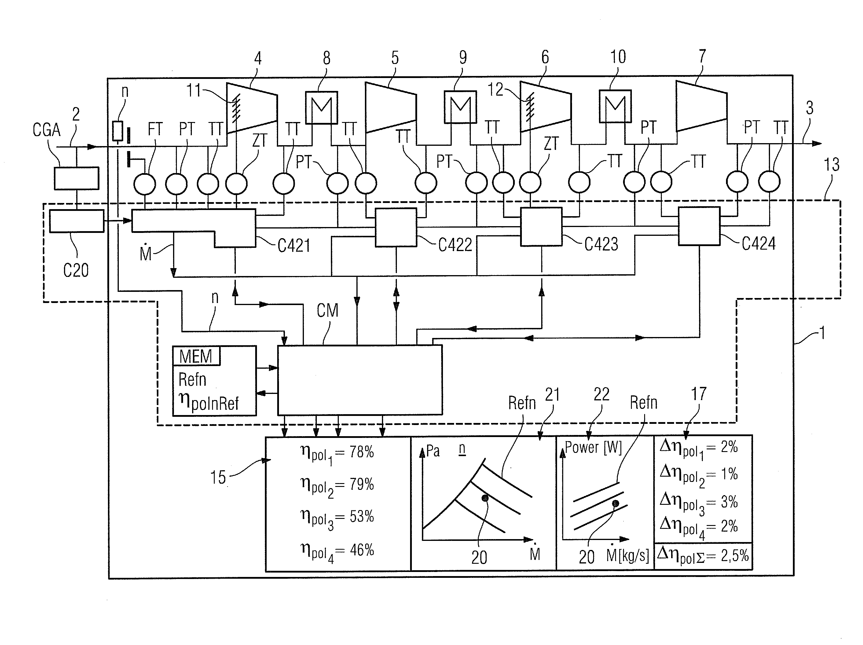
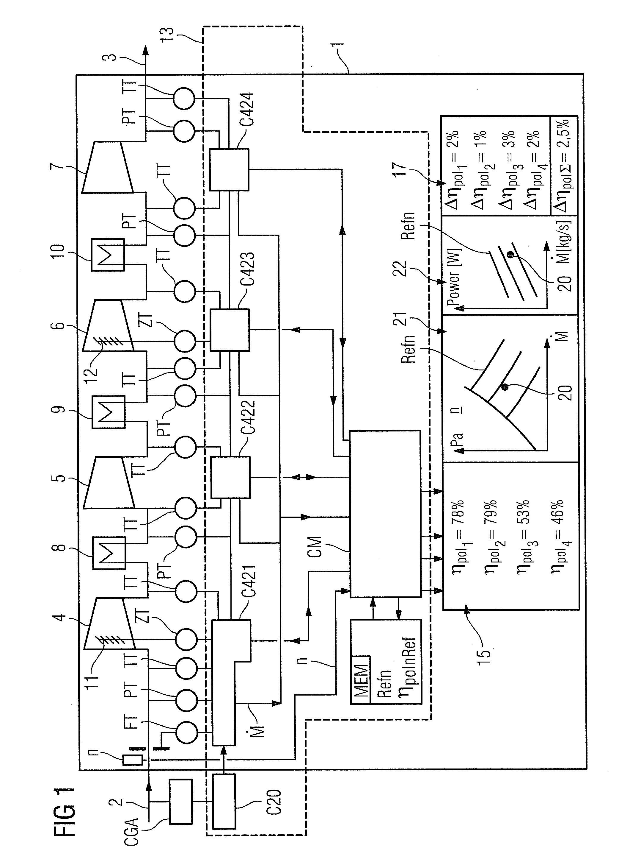
FIG. 1 is a schematic of a compressor 1 to which an inventive method for monitoring the efficiency is applied. A mass flow (measured as {dot over (M)}) enters the compressor 1 as entry mass flow 2, and exits it as exit mass flow 3. The compressor 1 has four stages 4, 5, 6, 7 (first stage 4 to fourth stage 7 correspondingly from left to right) which are traversed by the entry mass flow 2, an intermediate cooling stage 8, 9, 10 (numbering mutatis mutandis) being provided between the stages in each case.

Before entry into each stage 4, 5, 6, 7, and after exit from each stage 4, 5, 6, 7, in each case the pressure is measured by means of a pressure measuring point PT, and the temperature is measured by means of a temperature measuring point TT. Since, apart from a pressure loss in the intermediate cooling stage 8, 9, 10 that is small and can be understood, the pressure upstream of the intermediate cooling stage 8, 9, 10 and downstream of the intermediate cooling stage 8, 9, 10 is identica...


PUM


Abstract

A method for monitoring the efficiency of a compressor is provided. A mass flow, an entry pressure, an exit pressure, an entry temperature, and an exit temperature of the process medium are all determined and a performance factor is ascertained. At the inlet of each stage, a stage entry temperature and a stage entry pressure are directly or indirectly measured as measurement parameters. At the outlet of each stage, a stage exit temperature and a stage exit pressure are directly or indirectly measured as measurement parameters. Each stage is assigned a module which calculates a stage efficiency as a performance factor from the measurement parameters using a calculation means.

Description

FIELD OF INVENTIONThe invention relates to a method for monitoring the efficiency of an at least two stage compressor, an intermediate cooling stage being provided between the stages, during the compression of a process medium, in the case of which monitoringa flow rate through the compressor,an entry pressure of the drawn-in process medium,an exit pressure of the compressed process medium,an entry temperature of the drawn-in process medium, andan exit temperature of the compressed process mediumare determined as parameters, and calculation means are used to ascertain a performance factor from the parameters.BACKGROUND OF INVENTIONThe monitoring of turbocompressors continuously in operation essentially presently comprises the following variables: shaft oscillation and shaft position, bearing temperatures and other variables in the case of which it is possible to infer the state of a component or of a part of a system for a single measurement. With regard to economic operation of a c...

Claims


Application Information

Patent Timeline
Patent Type & Authority Applications(United States)
IPC IPC(8): G06F15/00
CPCG01M15/14F04D27/001
Inventor NUHSE, ANDREASWINKES, GEORG
Owner SIEMENS AG
Why Eureka
Try Eureka