Eureka AIR delivers breakthrough ideas for toughest innovation challenges, trusted by R&D personnel around the world.

Combustion Chamber for Charcoal Stove

Inactive Publication Date: 2011-05-19
COLORADO STATE UNIVERSITY
View PDF64 Cites 8 Cited by
  • Summary
  • Abstract
  • Description
  • Claims
  • Application Information

AI Technical Summary

Benefits of technology

[0018]The stove described and claimed herein may help decrease the amount of at least carbon monoxide produced during combustion of biomass, for example charcoal.
[0019]The present disclosure describes a metal biomass stove that may lower production costs while increasing durability and reducing its fuel consumption and CO emission. The stove combustion chamber may be designed to reduce the amount of, at least, carbon monoxide gas emitted from burning a solid fuel energy source by increasing the combustion temperature of the stove. This increase in combustion temperature may be achieved by increasing air flow, decreasing waste energy lost to thermal mass and unproductive radiative heat transfer.
[0020]FIG. 1 is a graphical comparison modeling CO oxidation at varying temperatures provided by various stove designs. This graph shows that the increased combustion temperature provided by the current stove design may dramatically increase CO destruction in biomass stoves. This temperature dependence may lead to a “CO spike” during startup of a stove, which is when CO is being produced from combustion but temperatures are well below the temperatures that may lead to CO oxidation. In this graph at 1100° K [˜830° C.] oxidation of CO is nearly complete after 0.1 seconds. In comparison, at 802° K [˜530° C.], about 95% of the CO is still present after 3.0 seconds. Thus the stove currently described and claimed may aid in the rapid destruction or oxidation of CO as compared to other stove designs.

Problems solved by technology

This graph shows that the increased combustion temperature provided by the current stove design may dramatically increase CO destruction in biomass stoves.
This temperature dependence may lead to a “CO spike” during startup of a stove, which is when CO is being produced from combustion but temperatures are well below the temperatures that may lead to CO oxidation.

Method used


Image

  • Combustion Chamber for Charcoal Stove
  • Combustion Chamber for Charcoal Stove
  • Combustion Chamber for Charcoal Stove

Examples


example 1

Fuel Bed Temperature

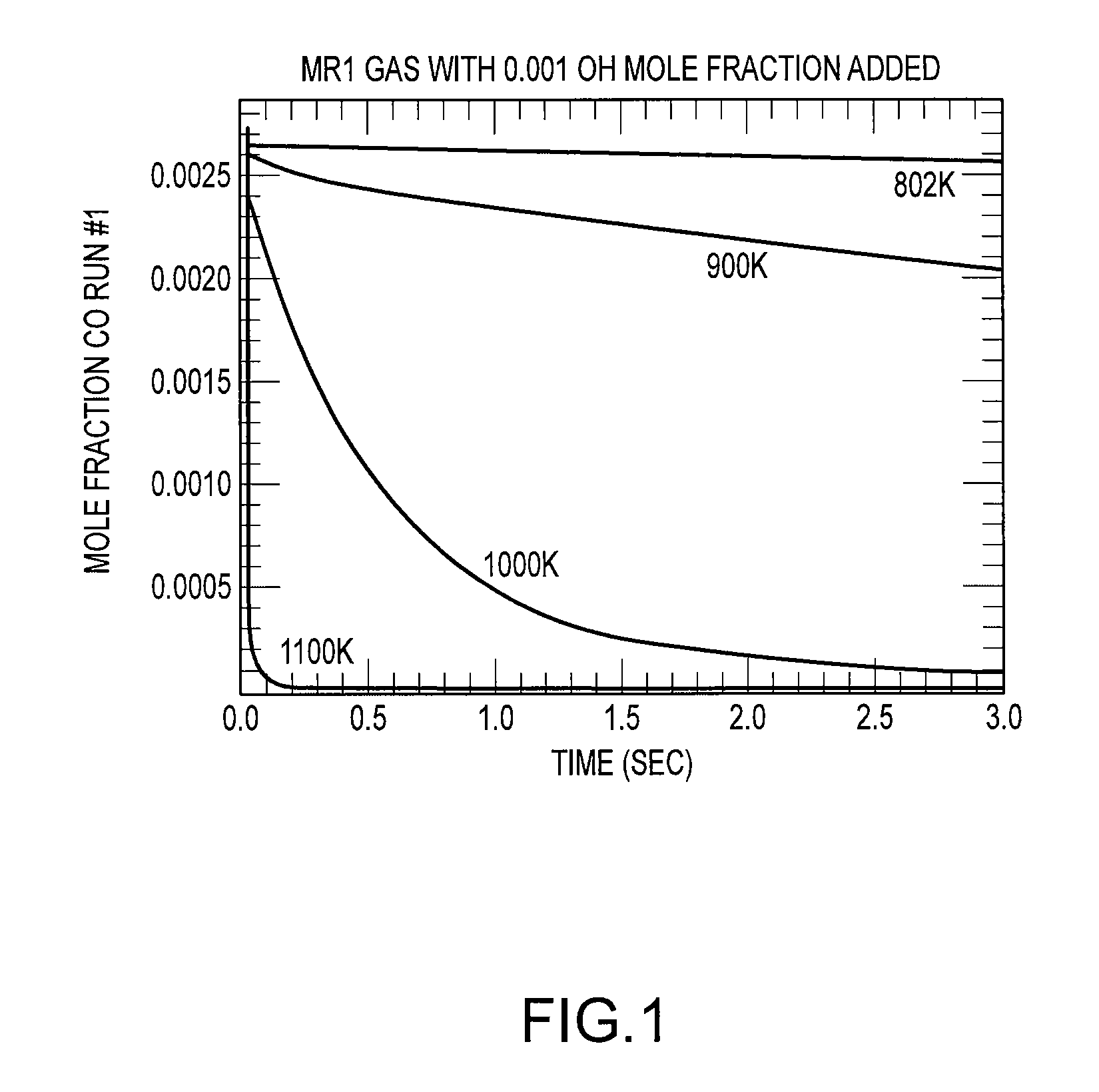
[0087]The present stove embodiment has been compared to the KCJ stove. To measure the temperature bed of the stoves, a thermocouple was placed within the coal beds of the stove during operation. The present embodiment stove may offer an addition 10% increase in thermal efficiency over the KCJ stove. The present embodiment charcoal stove burns at much higher temperatures than the KCJ stove. For example, the top of charcoal fuel bed of the present stove reaches temperatures estimated at greater than 1100° K [˜830° C.], while the KCJ stove's fuel bed reaches temperatures of about 900-1000° K [˜630-˜730° C.]. The present charcoal stove shows about a 10% increase in burn rate and approximately double the airflow rate.

example 2

CO Emission and Thermal Efficiency

[0088]The presently embodied charcoal stove shows a reduction in CO emission. Stove emissions were measured using testing protocols described in DeFoort, M.D., L'Orange, C., Kreutzer, C., Lorenz, N., Kamping, W, and Alders, J., Stove Manufacturers Emissions &Performance Test Protocol (EPTP). See Appendix A. Briefly, The EPTP takes approximately 1.5-2 hours and consists of three phases performed three times in sequence with modifications for charcoal stoves. Phase 1, the cold-start (CS) test, is a high-power test wherein the tester begins with the stove at room temperature and uses a pre-weighed bundle of wood or other fuel to heat a measured quantity of water to 90° C. in a standard pot. Phase 2, the hot-start (HS) high-power test, immediately follows the first test, and is performed while the stove is still hot. In the hot-start, the tester first replaces water heated in phase 1 with a fresh pot of cold water at the established starting temperature...

example 3

Chemical Kinetics Modeling of CO Oxidation

[0091]Compared to the KCJ stove, the present stove embodiment runs at higher temperatures, has increased oxygen flow, and longer residency times. Stove flow rates may be measured by standard measurements of oxygen and carbon balance.

[0092]The higher burn rate has an obvious effect on time to boil. Assuming similar thermal efficiencies, the higher burn rate supplies more energy to heat the pot. Increasing temperature is also the most direct way to increase both radiative and convective heat transfer rates to the pot. Convective transfer is also helped by the increased airflow in the present stove embodiment.


PUM


Abstract

A combustion chamber may include an upper and a lower chamber. The chambers may be separable to aid in loading fuel and removing spent fuel. The cross-section of the upper combustion chamber may be less than the cross-section of the lower section. Charcoal or other biomass fuel may be added into the lower combustion chamber and may be supported by a grate. Oxygen may be fed into the combustion chamber through a plurality of apertures that may be substantially shielded from direct line of site of the fuel bed. The upper combustion chamber may further include an annular constriction, to aid in constricting the view factor between the cooking vessel and the fuel bed. The constriction may also aid in radiating energy back to the fuel bed.

Description

CROSS REFERENCE TO RELATED APPLICATIONS[0001]The present application claims benefit of priority under 35 U.S.C. §119(e) to U.S. Provisional Application No. 61 / 261,694, filed Nov. 16, 2009. This application is related to U.S. provisional application No. 61 / 168,538, titled Cook Stove Assembly, filed on Apr. 10, 2009, and which is hereby incorporated by reference.BACKGROUND OF THE INVENTION[0002]The present invention relates generally to stoves and cooking apparatus for use in confined areas.[0003]About half of the world's population cooks over a biomass fire. Use of biomass as an energy source has lead to deforestation as well as a decrease in indoor air quality. In Africa, this biomass fuel source is typically charcoal.[0004]Charcoal stoves may burn relatively smoke free (i.e. low production of particulate matter), however they tend to produce high levels of carbon monoxide (CO). This may be caused by inefficient or incomplete combustion of charcoal fuel. While production of CO may n...

Claims


Application Information

Patent Timeline
IPC IPC(8): F24B5/02
CPCF24B1/202F24B1/022F24B1/26F24B5/023
Inventor DEFOORT, MORGAN W.KREUTZER, CORYBABBS, SEANAGENBROAD, JOSHL'ORANGE, CHRISTIAN
Owner COLORADO STATE UNIVERSITY
Why Eureka
Eureka Blog
Learn More