
Metal fitting integration type stress-relief cone and a cable sealing end using the same

a stress relief cone and metal fitting technology, applied in the direction of electrical apparatus casings/cabinets/drawers, emergency protective arrangements for limiting excess voltage/current, etc., can solve the problem of difficult point to arrange pressure devices, complex structure, and deterioration of workability, so as to achieve easy integration and strong integration

Inactive Publication Date: 2011-05-19
SWCC SHOWA CABLE SYST CO LTD
View PDF3 Cites 5 Cited by
  • Summary
  • Abstract
  • Description
  • Claims
  • Application Information

AI Technical Summary

Benefits of technology

[0012]According to the metal fitting integration type stress-relief cone of third feature from first feature of this invention, there are following effects.
[0013]First, by providing integrally the metal fitting at the low voltage side of the stress-relief cone comprising the rubber-like elastic body, the O-ring can be arranged at the sealing surface. Therefore, the sealing part (oil-stopping part) can be formed easily without using the metal fitting or the sealing tape which are used only for oil-stopping as before.
[0014]Second, by providing integrally the cylindrical insulation protective layer at the outer circumference of the semi-conducting body part of the stress-relief cone, the insulating oil which is filled in the inside of the porcelain bushing does not contact to the semi-conducting body part of the stress-relief cone. Therefore, there is not a fear that the physical property of the semi-conducting body part is influenced.
[0015]Third, by providing the depressed part at the inner edge of the end of the high-voltage side of the insulating body part of the stress-relief cone, the electric-field concentration in the triple junction which are the insulating fluid in the end of the high-voltage side of the stress-relief cone, the insulating body part of the stress-relief cone, and the cable insulator of the cable core can be prevented.
[0016]Fourth, by protruding and providing the semi-conducting skirt part and the insulating skirt part at the low-voltage side of the stress-relief cone, and by providing the cylindrical part in the metal fitting, the metal fitting and the stress-relief cone can be integrated strongly.
[0017]Fifth, by providing the annular protrusion at the inner circumference of the end of the low-voltage side of the insulating skirt part which constructs the stress-relief cone, and by providing the annular concave groove which engages with the aforementioned protrusion at the end of the low-voltage side of the second cylindrical part which constructs the metal fitting, the metal fitting and the stress-relief cone can be integrated more strongly. Concretely, by this constitution, in the case of not only the integration of the stress-relief cone and the metal fitting by molding but also the integration of the stress-relief cone and the metal fitting by expanding the diameter of the stress-relief cone and installing to the metal fitting at the construction site, the stress-relief cone and the metal fitting can be integrated more strongly.

Problems solved by technology

However, in the cable sealing end of (1), although the decision of the position of the molded rubber stress-relief cone can be performed easily, because the predefined interfacial pressure must be given to the interface between the molded rubber stress-relief cone and the epoxy unit, there is a difficult point which must arrange the pressure device having such as the relatively-large spring unit in the neighborhood of the molded rubber stress-relief cone.
Second, because it is necessary to provide the component such as the metal fitting which are used only for oil-stopping, and because the operation of winding of the sealing tape is necessary, the structure becomes complex and also the workability deteriorates.

Method used


Image

  • Metal fitting integration type stress-relief cone and a cable sealing end using the same
  • Metal fitting integration type stress-relief cone and a cable sealing end using the same
  • Metal fitting integration type stress-relief cone and a cable sealing end using the same

Examples


embodiment 1

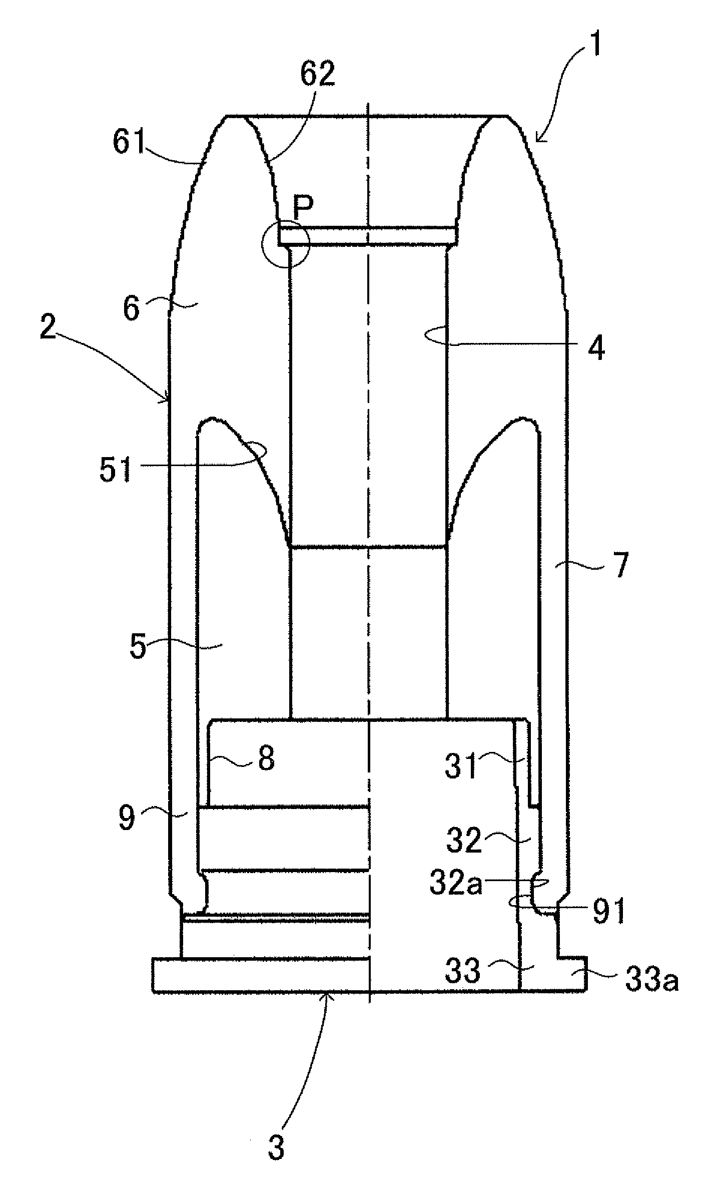
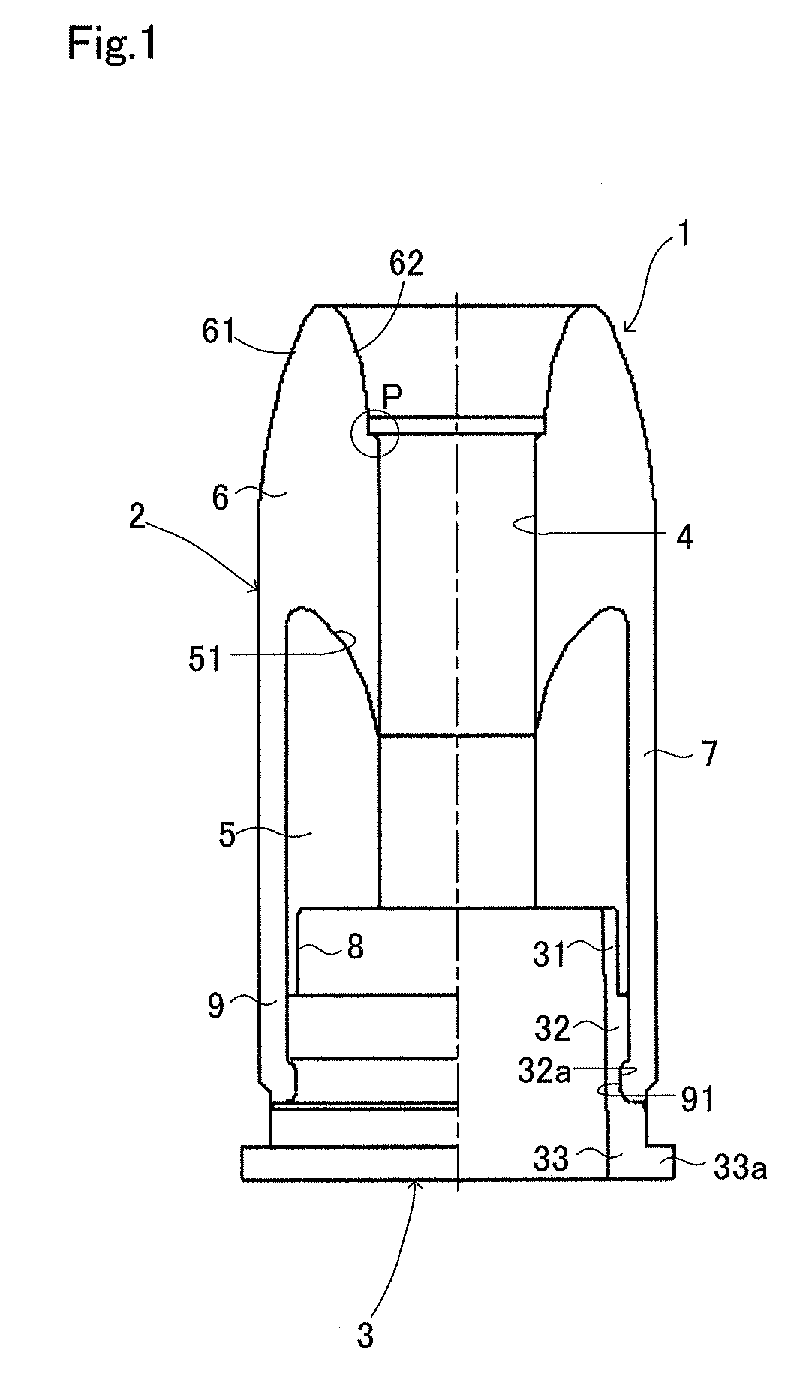
[0044]FIG. 1 shows the partial sectional view of the metal fitting integration type stress-relief cone of this invention which is suitable to the indoor / outdoor termination of 110 kV class.

[0045]In this drawing, the metal fitting integration type stress-relief cone 1 of this invention is provided with the stress-relief cone 2 comprising the rubber-like elastic body which is installed at the outer circumference of the after-mentioned cable core 11 (refer to FIG. 2), and the metal fitting 3 which surrounds the cable core 11 and is provided integrally at the low-voltage side of the stress-relief cone 2, and shows the cylindrical shape totally. In this embodiment, the total length of the metal fitting integration type stress-relief cone 1 is about 405 mm, and the outer diameter of the stress-relief cone 2 is about 180 mm, besides, the inner diameter of the insertion hole 4 which is provided at the center of the stress-relief cone 2 is about 64 mm.

[0046]The stress-relief cone 2 is provid...

embodiment 2

[0058]Next, the cable sealing end in this invention is explained.

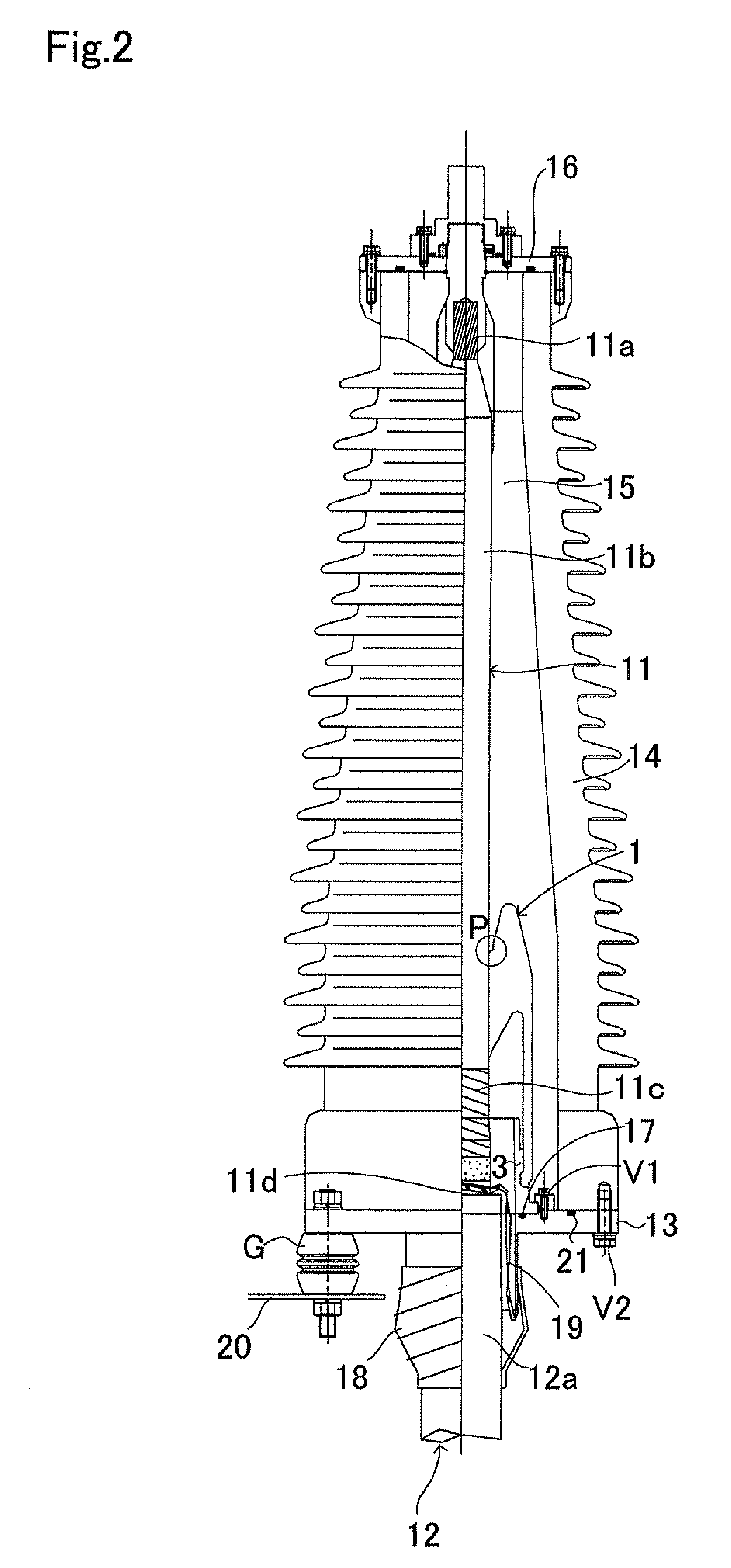
[0059]FIG. 2 shows the partial sectional view of the indoor / outdoor termination of 110 kV class using the metal fitting integration type stress-relief cone 1 of this invention. Meanwhile, in this drawing, the same numerals are given to the portions which are common to FIG. 1, and detailed explanation is omitted.

[0060]In FIG. 2, the cable sealing end of this invention is provided with the cable termination 12 whose cable core 11 is exposed by the step-stripped process, the porcelain bushing 14 which surrounds the cable termination 12, the insulating fluid 15 which is filled in the inside of the porcelain bushing 14, and the metal fitting integration type stress-relief cone 1 shown in embodiment 1.

[0061]The cable sealing end of such a constitution is assembled as follows.

[0062]First, the annular lower metal fitting 13 is fixed through the supporting insulator G and so on at the neighborhood of the end of the cable sheath...

embodiment 3

[0068]Next, the cable sealing end concerning other embodiment of this invention is explained.

[0069]FIG. 3 is the explanation view which shows the state of the assembling of the indoor / outdoor termination of 110 kV class concerning other embodiment of this invention. Meanwhile, in this drawing, the same numerals are given to the portions which are common to FIG. 1 and FIG. 2, and detailed explanation is omitted.

[0070]In this embodiment, as shown in FIG. 3(a), the semi-conducting body part 5, the insulating body part 6, the insulation protective layer 7, the semi-conducting skirt part 8 and the insulating skirt part 9 which construct the stress-relief cone 2 which is shown in FIG. 1 are preliminarily integrated by molding in the factory. Meanwhile, the stress-relief cone 2 which is formed by the rubber-like elastic body has the cold shrinkable property.

[0071]Besides, in the inner circumference side of the cylindrical stress-relief cone 2 which is formed in this way, the cylindrical di...


PUM


Abstract

A metal fitting integration type stress-relief cone is provided with a stress-relief cone which includes a cylindrical rubber-like elastic body on an outer circumference of a cable core and a metal fitting which surrounds the cable core and is integral with a low-voltage side of the stress-relief cone. The stress-relief cone is provided with a cylindrical semi-conducting body part at the low-voltage side and has a bell-mouthed electric-field stress-control part in an end of a high-voltage side, an insulating body part on the high-voltage side with a low-voltage side end concentric with the semi-conducting body part and a cylindrical insulation protective layer which is arranged continuously at the end of the low-voltage side of the insulating body part and is integral with the outer circumference of the semi-conducting body part

Description

TECHNICAL FIELD[0001]This invention relates to a metal fitting integration type stress-relief cone and a cable sealing end using the metal fitting integration type stress-relief cone. Particularly, it relates to the metal fitting integration type stress-relief cone which can reduce the number of components and considerably improve the sealing characteristic of the sealing part (oil-stopping part), and relates to the cable sealing end using the metal fitting integration type stress-relief cone.BACKGROUND ART[0002]Heretofore, as this kind of the cable sealing end, (1) the thing which fixes an epoxy unit in the inside of a base of a porcelain bushing and installs a molded rubber stress-relief cone to the aforementioned epoxy unit (for example, refer to Patent document No. 1), or (2) the thing which controls the electric field by the molded rubber stress-relief cone itself without providing the above-mentioned epoxy unit (for example, refer to Patent document No. 2) are known.[0003]Howe...

Claims


Application Information

Patent Timeline
Patent Type & Authority Applications(United States)
IPC IPC(8): H02G15/00
CPCH02G15/064
Inventor TAKAYASU, HISAYASEMA, NOBUYUKI
Owner SWCC SHOWA CABLE SYST CO LTD
Learn More