Gas delivery for beam processing systems

a beam processing and gas delivery technology, applied in the direction of liquid/fluent solid measurement, liquid transfer device, rigid container, etc., can solve the problems of limited crucible capacity, limited control of temperature and valve opening, limited control ability of equipment in the field, etc., to achieve rapid response and easy connection or disconnection

Active Publication Date: 2011-05-19
FEI CO
View PDF45 Cites 30 Cited by
  • Summary
  • Abstract
  • Description
  • Claims
  • Application Information

AI Technical Summary

Benefits of technology

[0012]In accordance with some preferred embodiments, gas flow from multiple gas sources into a sample chamber of a beam system is controlled by a cycling valve for each gas source, with the gas pressure in the sample chamber being determined by the relative time that the valve is opened and the upstream pressure at the valve. A gas valve positioned inside the vacuum chamber allows rapid response in shutting off a gas.
[0013]In accordance with some preferred embodiments, a precursor gas is supplied from a solid or liquid material in a container that remains outside the vacuum system while in use and which is readily connected or disconnected to the gas injection system without significant leakage.

Problems solved by technology

The limited crucible capacity requires frequent refilling of the crucible in many applications.
The dangerous nature of some of the precursor chemicals necessitates special safety equipment during refilling, which equipment may not be readily available in the field.
Controlling the temperature and the valve opening provides a limited ability to control the pressure within the sample chamber of the charged particle beam system.
Control of pressure of the precursor gas in the charged particle beam sample chamber is limited in prior art systems because the pressure is controlled only by the controlling the temperature of the gas source or the degree of opening of the diaphragm valve.
Such apertures, however, increase the time required to bring the sample chamber up to the desired operating pressure.
That is, a valve setting that provides a first sample pressure chamber on the first system will not necessarily provide the same pressure on a second system.
It can be difficult to maintain the desired ratio when control of each component is inexact.
Use of a single main line leaves precursor gas in the main line when the crucible valve is closed, thereby requiring a purging procedure for the main line, which takes time and wastes precursor gas.

Method used


Image

  • Gas delivery for beam processing systems
  • Gas delivery for beam processing systems
  • Gas delivery for beam processing systems

Examples


Embodiment Construction

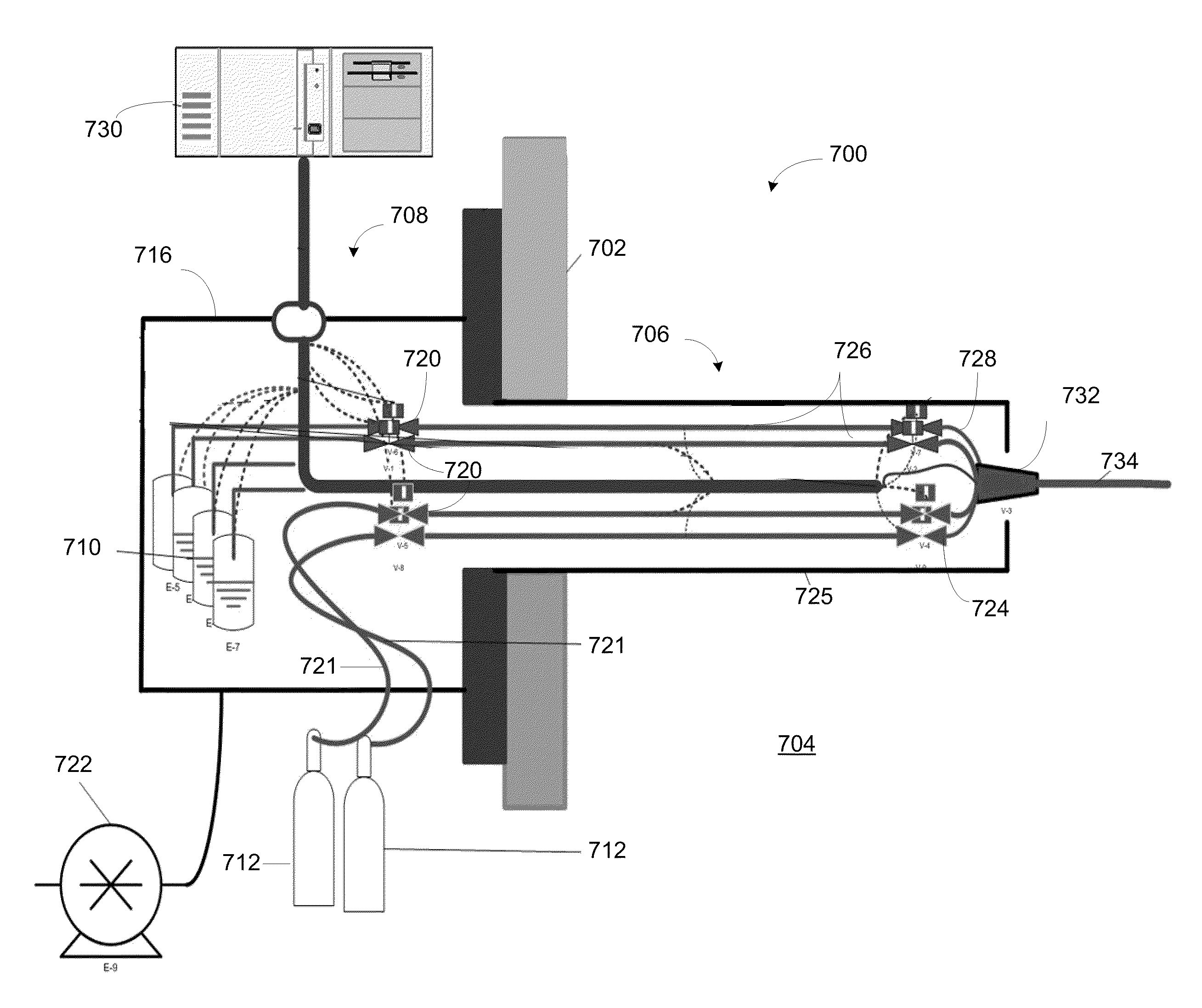
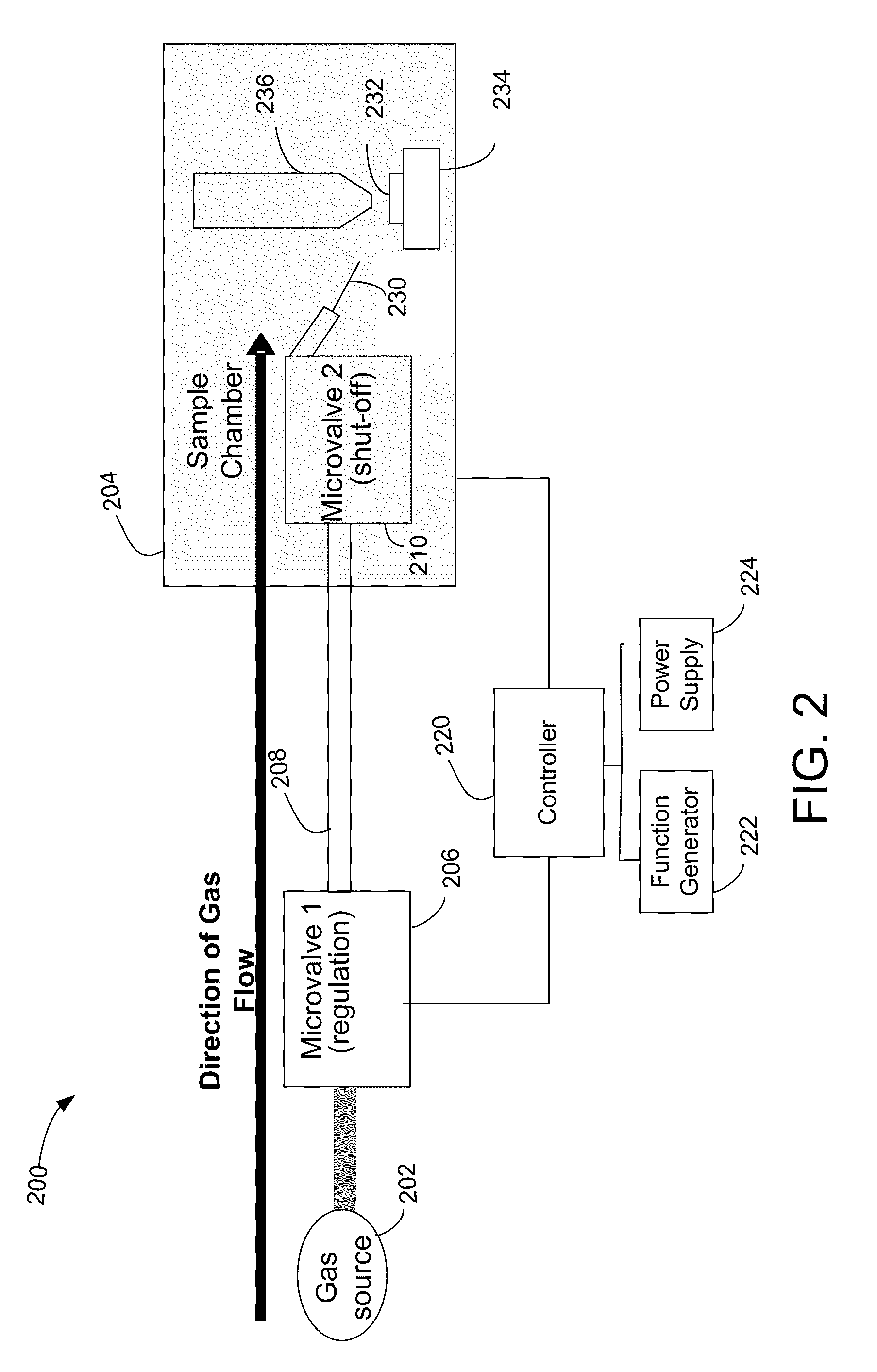
[0024]In accordance with a preferred embodiment of the present invention, the gas flow into a sample chamber of a beam system is controlled by a “cycling” valve, such as a microvalve. A cycling valve, as used herein, means a valve that controls a flow by cycling between an open position and closed position, with the flow being controlled by the fraction of time during a given period that the valve is open. By cycling the valve rapidly, typically at a frequency greater than one Hertz, the gas flow can be averaged out to the extent required by the application. Both the time that the valve remains open during each cycle and the number of cycles per second, that is, the cycle frequency can be adjusted to control the gas flow through the valve. The percentage of time that the valve is open is referred to a “duty cycle.” The flow will also be determined, of course, by the pressure difference across the valve. In most applications the pressure in the sample chamber is much lower than the g...


PUM

PropertyMeasurementUnit
temperatureaaaaaaaaaa
frequencyaaaaaaaaaa

Abstract

Gas flow from multiple gas sources into a sample chamber of a beam system is controlled by a cycling valve for each gas source, with the gas pressure in the sample chamber being determined by the relative time that the valve is opened and the upstream pressure at the valve. A gas valve positioned inside the vacuum chamber allows rapid response in shutting off a gas. In some preferred embodiments, a precursor gas is supplied from a solid or liquid material in a container that remains outside the vacuum system while in use and which is readily connected or disconnected to the gas injection system without significant leakage.

Description

[0001]This Application claims priority from U.S. Provisional Application 61 / 261,622, filed Nov. 16, 2009, which is hereby incorporated by reference.TECHNICAL FIELD OF THE INVENTION[0002]The present invention relates to systems for providing a gas for a beam processing system, ion beam or electron beam system.BACKGROUND OF THE INVENTION[0003]Beam systems, such as electron beam systems, ion beam systems, laser beam systems, cluster beam system, and neutral particle beam systems, are used to create features on a surface by etching or deposition. Beam-induced deposition processes use a precursor gas that reacts in the presence of the beam to deposit material on the surface in areas where the beam impacts. For example, a gaseous organometallic compound, such as tungsten hexcarbonyl, is provided near the sample and is adsorbed onto the surface. The organometallic compound decomposes in the presence of a charged particle beam, such as an ion beam or an electron beam, to form a metal that r...

Claims


Application Information

Patent Timeline
Patent Type & Authority Applications(United States)
IPC IPC(8): B67D7/36B65D23/00
CPCC23C16/047C23C16/4485H01J2237/006C23C16/45561C23C16/45523
Inventor CHANDLER, CLIVE D.RANDOLPH, STEVENHARTIGAN, GAVIN
Owner FEI CO
Why Eureka
Try Eureka