Targeted mass mailing system and method

a mailing system and mass technology, applied in the field of targeted mass mailing system and method, can solve the problems of high investment cost and high operational cost of conventional processes, and achieve the effect of facilitating the transference of sets during processing and efficient design of glue tack application

Inactive Publication Date: 2011-05-19
DONAHUE PATRICK J
View PDF51 Cites 2 Cited by
  • Summary
  • Abstract
  • Description
  • Claims
  • Application Information

AI Technical Summary

Benefits of technology

[0008]The present invention provides a system and method for pre-engineering subassemblies from modules designed to handle the variety and flexibility required to feed, trim and then transfer the subassemblies into most known finishing equipment such as rotary, reciprocal, or in-line inserters. The subassemblies may be fed by vacuum belts, lug belts, grippers, friction feeders or any other manner of timed feeding. The invention has also made allowances for transference of the subassemblies into roll collator type devices, in-line finishing systems and wrapping devices or envelopers. There is an almost endless variety of possible subassembled, pre-engineered mailing package sets that may be created due to the pre-engineering of short or long folds (or both), the ability to include ribboning, pre-slitting and / or slit and nest, the ability to pre-engineer slitting and / or die cutting for the subsequent creation of loose and / or different sized and folded components, as well as the ability to efficiently design the application of glue tacks and / or crimp welds to facilitate the transference of the sets during processing. The invention also contemplates the location of turnover and change of direction devices throughout the process since differing orientations of the subassembly may be needed in the final carrier package in order to employ the most cost-efficient subassembly production methods.

Problems solved by technology

Consequently, the high investment costs and high operational costs of conventional processes are no longer barriers to entry to smaller marketers.

Method used


Image

  • Targeted mass mailing system and method
  • Targeted mass mailing system and method
  • Targeted mass mailing system and method

Examples


Embodiment Construction

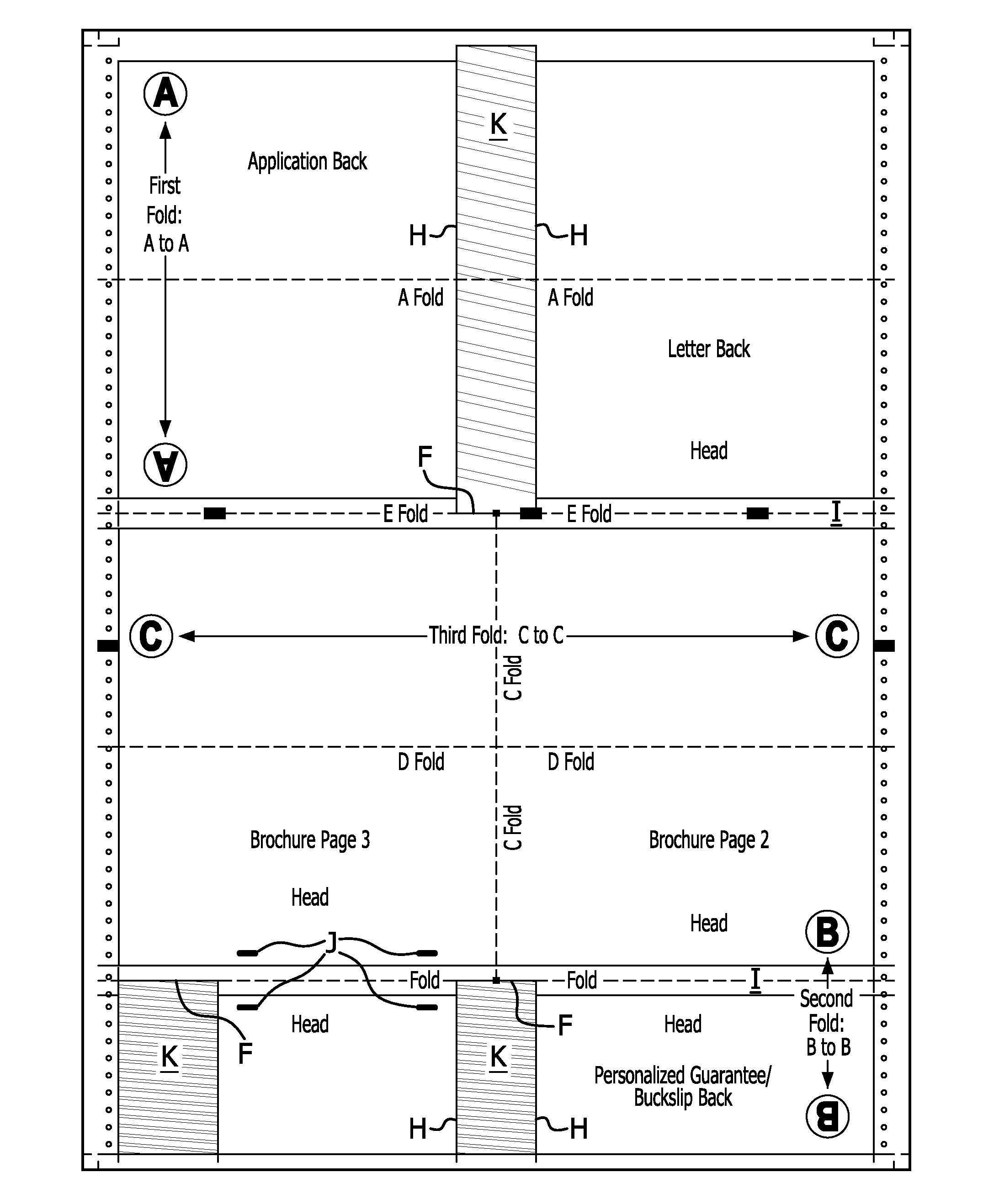
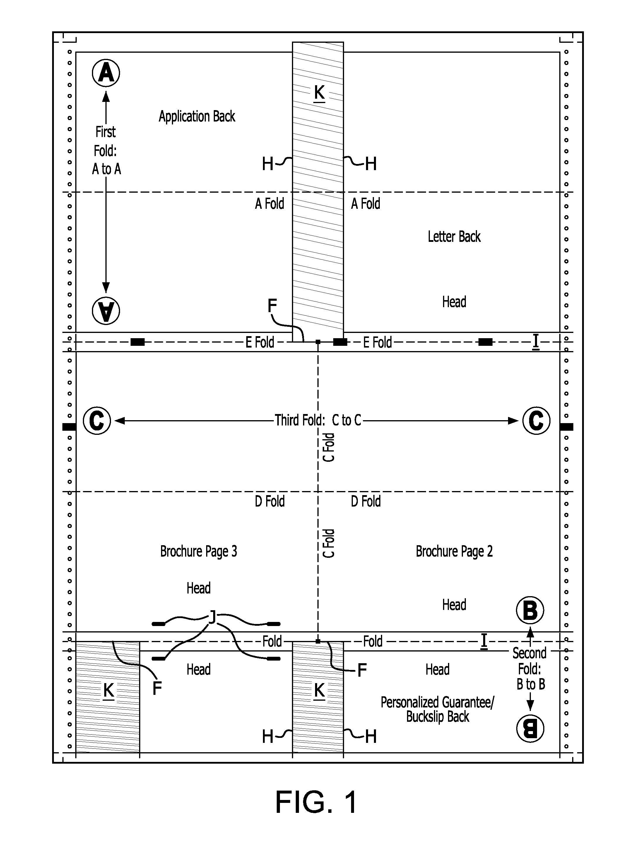
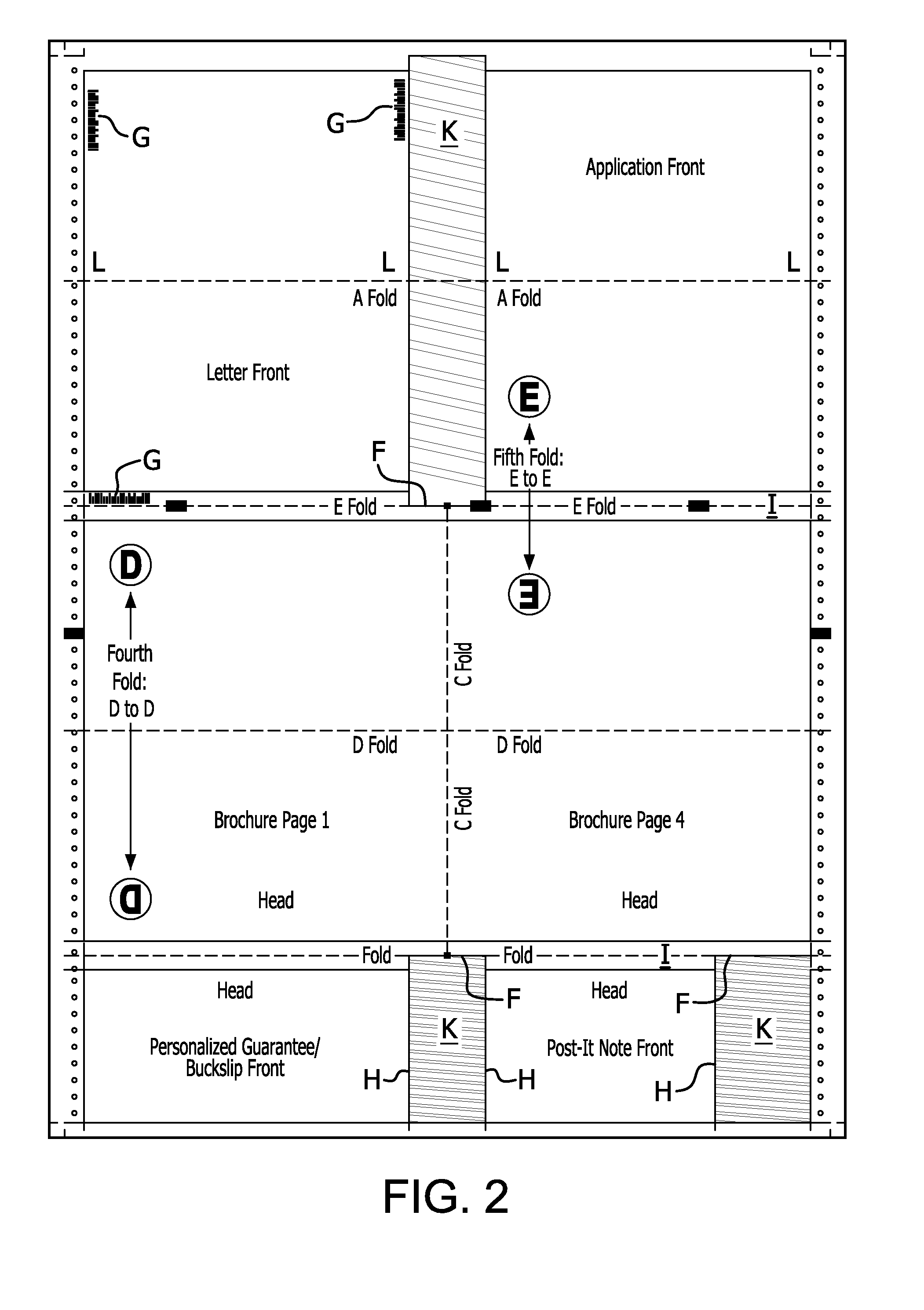
[0039]Referring to the drawings, there is shown in FIGS. 1 and 2 a pre-engineered subassembly according to the present invention, the subassembly being identified generally by reference numeral 10. As used herein the term “pre-engineered subassembly” shall mean a unit of printable substrate which is processed according to at least one client-specified rule and which includes a unique identifier linked to associated code that controls manufacturing of the subassembly into a final assembly that constitutes at least one component of a mailing package, wherein the printable substrate comprises paper, cardboard, plastic, foil, or the like, or any combination of the foregoing, wherein the at least one component includes at least one mailing package insert and / or a mailing package container (e.g., an envelope, box, or the like), wherein processing includes, but is not limited to, at least one of printing, folding, cutting, perforating, trimming, gluing, slitting, die-cutting, personalizing...


PUM


Abstract

A targeted mass mailing system and method including use of a pre-engineered subassembly. The subassembly is a unit of printable substrate which is processed according to at least one client-specified rule and which includes a unique identifier having associated code that drives manufacturing of the subassembly into a final assembly that constitutes at least one component of a mailing package, wherein the printable substrate may include at least one of paper, cardboard, plastic and foil, wherein the at least one component includes at least one mailing package insert and/or a mailing package container, wherein processing includes, but is not limited to, at least one of printing, folding, cutting, perforating, trimming, gluing, slitting, die-cutting, personalizing, matching, tipping, affixing, inserting, flipping, inverting, on-serting, labeling, enclosing and enveloping of the unit, and wherein the unique identifier is preferably removable.

Description

CROSS REFERENCE TO RELATED APPLICATION[0001]This application claims the benefit of U.S. Provisional Application No. 61 / 261,423, filed Nov. 16, 2009.FIELD OF THE INVENTION[0002]The present invention relates to a system and method for utilizing multiple print and personalization technologies for the production of highly personalized, segmented and customized mailing packages.BACKGROUND OF THE INVENTION[0003]Conventional print advertising mailings have been decreasing both in total volume and the size of individual campaigns. Printed advertising mail has succumbed to the speed and lower cost of electronic mail (“e-mail”) campaigns and to the proliferation of segmented advertising opportunities presented by cable, satellite and digital TV programming. The ability of electronic media to deliver targeted advertising to smaller audiences, with increased frequency and variation of copy—and at low cost—has created a difficult competitive climate for print media. Mass print mailings cannot of...

Claims


Application Information

Patent Timeline
Patent Type & Authority Applications(United States)
IPC IPC(8): B42D15/00B31B41/00
CPCB43M3/04B42D15/00
Inventor DONAHUE, PATRICK J.
Owner DONAHUE PATRICK J
Why Eureka
Try Eureka