Starter for an internal combustion engine

a technology of an internal combustion engine and a starter, which is applied in the direction of engine starters, machines/engines, electric generator control, etc., can solve the problems of high dynamic response high contact wear, and difficult working conditions of the switching process, so as to avoid reactions

Inactive Publication Date: 2011-05-19
ROBERT BOSCH GMBH
View PDF9 Cites 11 Cited by
  • Summary
  • Abstract
  • Description
  • Claims
  • Application Information

AI Technical Summary

Benefits of technology

[0003]The starter according to the invention, has the advantage that the processes for engagement of the pinion on the one hand and the switching of the motor current on the other hand are completely decoupled by the use of separate means for this purpose, in particular by the use of separate relays, in which case, the types of relay can be optimally matched to the respective process steps. However, it is also possible to use suitable semiconductor components, preferably transistors or GTO (Gate Turn Off) thyristors, for switching relatively high currents for all of the switching means, or for individual switching means. In particular, this makes it possible to completely separate the switching function for the high main motor current during starting of the internal combustion engine from the engagement process, thus avoiding reactions from the engagement dynamics on the contact system of the relay. The speed at which the contacts close is in this case independent of the engagement situation.
[0004]It is particularly advantageous for the switching relay in the main circuit of the starter motor to be activated by the engagement relay itself at the end or shortly before the end of the engagement movement, and in this case for the starter motor to be connected directly to the voltage source. With little additional complexity, this results in exact interaction between the engagement movement of the pinion and the process of switching on the main starter current at the end of the engagement movement. The engagement relay is for this purpose expediently equipped with a holding winding and a separate pull-in winding, which jointly operate a switching contact for activation of the switching relay. The holding winding and the engagement winding are preferably seated on the same relay core, and are in this case selectively switched in the same sense or in opposite senses. If they are switched in the same sense, the required total flux is achieved with a smaller number of turns and / or a lower excitation current while, if the fluxes are opposite, the winding with the lesser flux can be used to damp the switching process. The numbers of turns and the excitation currents for the holding winding and the pull-in winding are in this case expediently chosen such that the holding winding produces the switching process of the engagement relay with a large number of turns and an adequate excitation current, while the pull-in winding is equipped with considerably fewer turns, but carries a considerably higher excitation current, which is sufficient to easily rotate the armature during engagement.
[0005]One particularly simple and cost-effective circuit design is obtained by current being passed through the starter motor in a single stage, in which case the pull-in winding of the engagement relay is connected in series with a series winding of the starter motor, as a bias resistance, and both windings of the engagement relay jointly switch a make contact, via which current is passed to the winding of the switching relay, and the starter motor is supplied with the entire motor current at the end of the pull-in movement of the engagement relay. As is known, an arrangement such as this requires an engagement spring which, in conjunction with a steep-pitched thread, in particular when the pinion and the toothed rim are in a so-called tooth-on-tooth position, assists the engagement process, before suddenly switching on the main current for the motor.

Problems solved by technology

This known starter design admittedly requires only a single relay and can therefore be produced at relatively low cost, but on the other hand it results in very difficult working conditions for the switching process for the high motor current on the switching contact which connects the motor windings to the voltage source.
On the other hand, if the pinion engages directly in the engine toothed rim, the dynamic response of the switching process and the contact wear resulting from it may possibly be high, depending on the design of the starter, when starting from an initial tooth-in-gap position.
This allows the engagement process and the switching of the main current of the motor to be carried out in two separate processes, but the design of the pull-in relay is more complex and more susceptible to defects, from the mechanical and electrical points of view.

Method used


Image

  • Starter for an internal combustion engine
  • Starter for an internal combustion engine
  • Starter for an internal combustion engine

Examples


Embodiment Construction

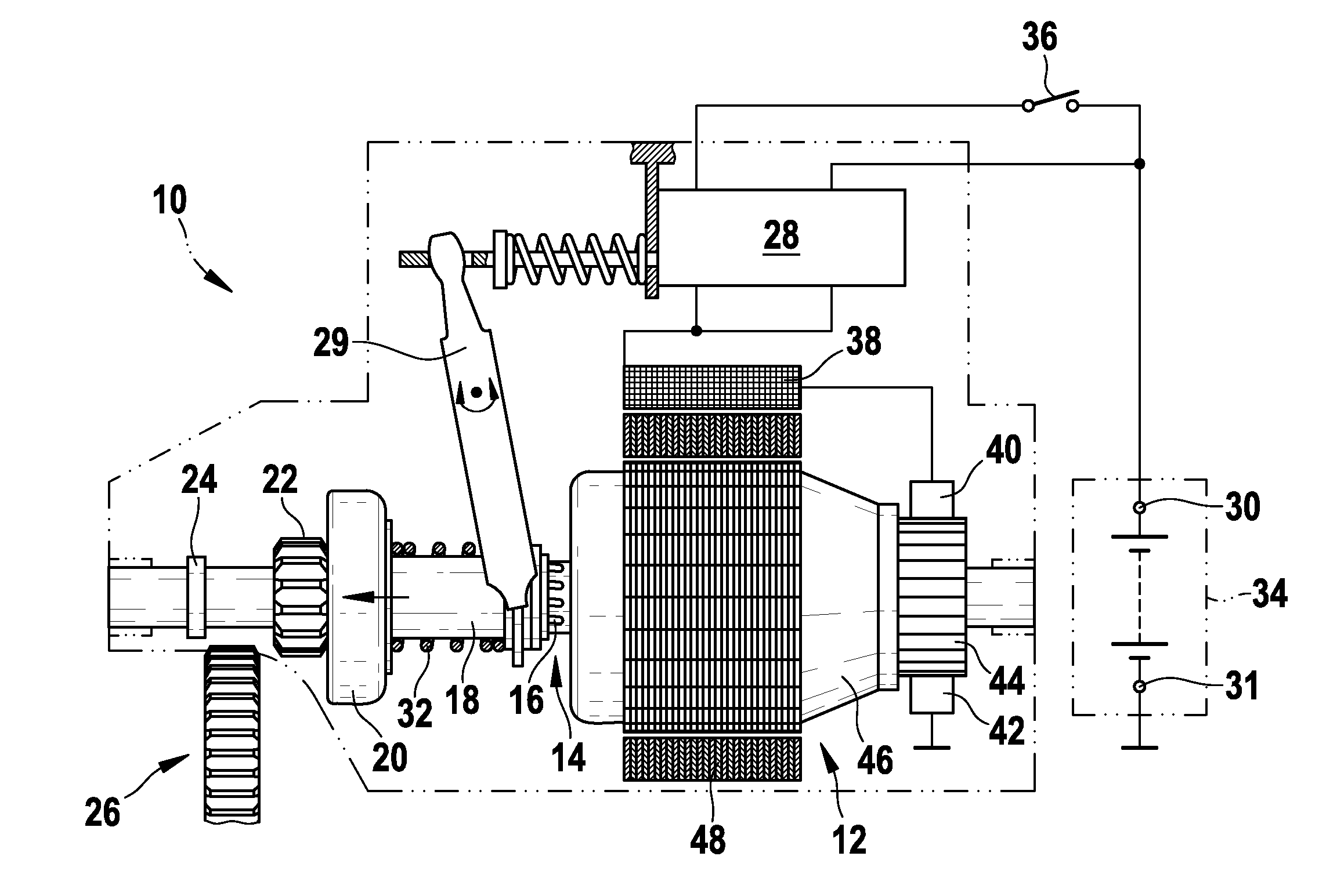
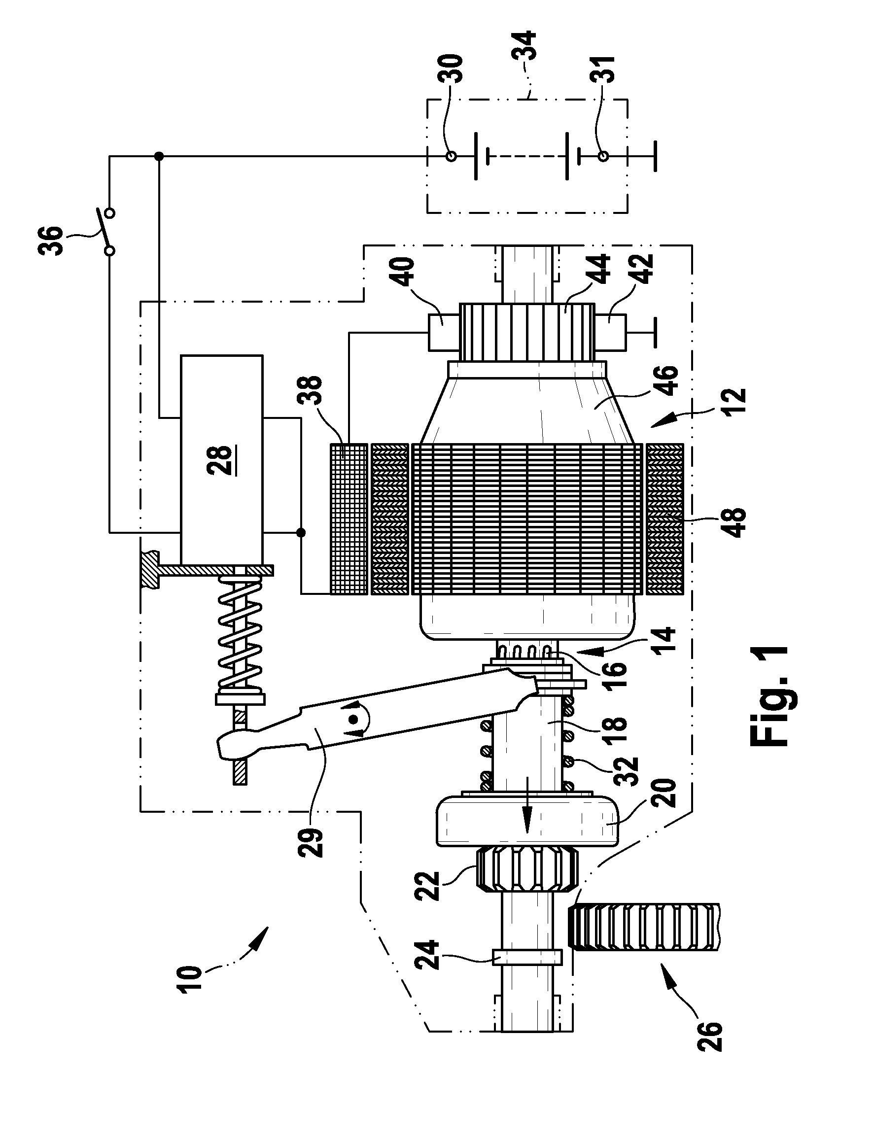
[0015]FIG. 1 schematically illustrates the mechanical design of the starter 10 according to the invention, in the form of a pre-engaged Bendix starter for an internal combustion engine. The starter 10 has a starter motor 12 whose output drive shaft 14 has a steep-pitched thread 16 which interacts with a corresponding female thread in a driver shaft 18. Alternatively, the output drive shaft 14 is driven via an epicyclic gearbox, which is connected in between, but is not illustrated. The driver shaft 18 is firmly connected to the outer ring of a freewheeling ring 20, whose inner ring is fitted with a pinion 22. The pinion 22 and the freewheeling mechanism 20 are mounted on the output drive shaft 14 such that they can move axially as far as a stop 24. The pinion 22 in this case engages in a toothed rim 26 of an internal combustion engine, which is not illustrated. The axial movement takes place with the aid of a relay arrangement 28, which is illustrated in detail in the following figu...


PUM


Abstract

The invention relates to a starter (10) for an internal combustion engine, comprising a starter motor (12) which can be coupled to the internal combustion engine by means of a pinion (22), and a device for engaging the pinion (22) in a gear rim (26) of the internal combustion engine and connecting the starter motor (12) to a DC voltage supply system (30, 31). In order to disconnect the sequence of operations, the device has separate means, in particular separate relays (57, 64; 60), for engaging the pinion (22) on one hand and turning on the starter motor on the other when the internal combustion engine is started, thus preventing reactions of the engagement dynamics on the contact system when the motor current is switched.

Description

BACKGROUND OF THE INVENTION[0001]The invention relates to a starter for an internal combustion engine. By way of example, one such starter is described in the Kraftfahrtechnischen Taschenbuch (Motor vehicle manual) produced by Bosch, 25th edition, page 986, in the form of a pre-engaged Bendix starter, which is operated via a so-called pull-in relay. This relay carries out the pulling-in functions, that is to say engaging the pinion of the starter motor in the toothed rim on an internal combustion engine, and switching the main current of the starter motor. In this case, a distinction can be drawn between two possible processes when the pinion engages in the toothed rim: in about 20%-30% of switching operations, one tooth of the pinion engages in a gap in the toothed rim, while, in approximately 70%-80% of the switching operations, one tooth of the pinion strikes a tooth on the toothed rim during engagement, and the engagement process must be assisted by an engagement spring. This kn...

Claims


Application Information

Patent Timeline
Patent Type & Authority Applications(United States)
IPC IPC(8): F02N11/08
CPCF02N11/0851F02N11/087F02N2011/0892F02N2011/0874F02N15/067
Inventor BIESSENBERGER, THOMASWANNER, HARTMUTDAURER, UWENEUMANN, OLIVER
Owner ROBERT BOSCH GMBH
Why Eureka
Try Eureka