Control System for Electric Vehicle, and Electric Vehicle Equipped Therewith

a technology for electric vehicles and control systems, applied in process control, battery/fuel cell control arrangements, instruments, etc., can solve the problems of insufficient attention to the overall energy efficiency of electric vehicles, and achieve the effects of reducing electrical power, and reducing electrical power discharge fluctuations

Inactive Publication Date: 2011-05-19
HITACHI LTD
View PDF9 Cites 20 Cited by
  • Summary
  • Abstract
  • Description
  • Claims
  • Application Information

AI Technical Summary

Benefits of technology

[0018]According to the 11th aspect of the present invention, in the control system for an electric vehicle according to any one of the 1st through 10th aspects, it is preferred that: a temperature regulation device that performs air conditioning of the interior of a passenger compartment or cooling of an onboard device is included in the plurality of load devices; there is further provided a thermal storage device that accumulates heat or cold generated by the electricity storage device and the plurality of load devices; and the temperature regulation device performs heating or air conditioning of the interior of the passenger compartment and cooling of an onboard device using heat or cold accumulated in the thermal storage device, thus reducing the electrical power supplied from the electricity storage device to the temperature regulation device.
[0019]According to the 12th aspect of the present invention, a control system for an electric vehicle, comprises: an electricity storage device that performs charging and discharging of electrical power; a plurality of load devices that receive s...

Problems solved by technology

However, with prior art devices such as described above, sufficient attention has not been paid to the overall energy efficiency of the electric vehicle whe...

Method used


Image

  • Control System for Electric Vehicle, and Electric Vehicle Equipped Therewith
  • Control System for Electric Vehicle, and Electric Vehicle Equipped Therewith
  • Control System for Electric Vehicle, and Electric Vehicle Equipped Therewith

Examples


embodiment 1

[0036]The first embodiment of the control system for an electric vehicle according to the present invention, and of an electric vehicle equipped therewith, will now be explained with reference to FIGS. 1 through 10. While in this first embodiment the present invention is shown as applied to an electric vehicle of the front wheel drive type, the present invention could also be applied to an electric vehicle of the rear wheel drive type or of the four wheel drive type, to a hybrid electric vehicle that is also provided with an internal combustion engine, or to an electric vehicle for construction, an electric vehicle for a railroad, or indeed an electric vehicle of any kind.

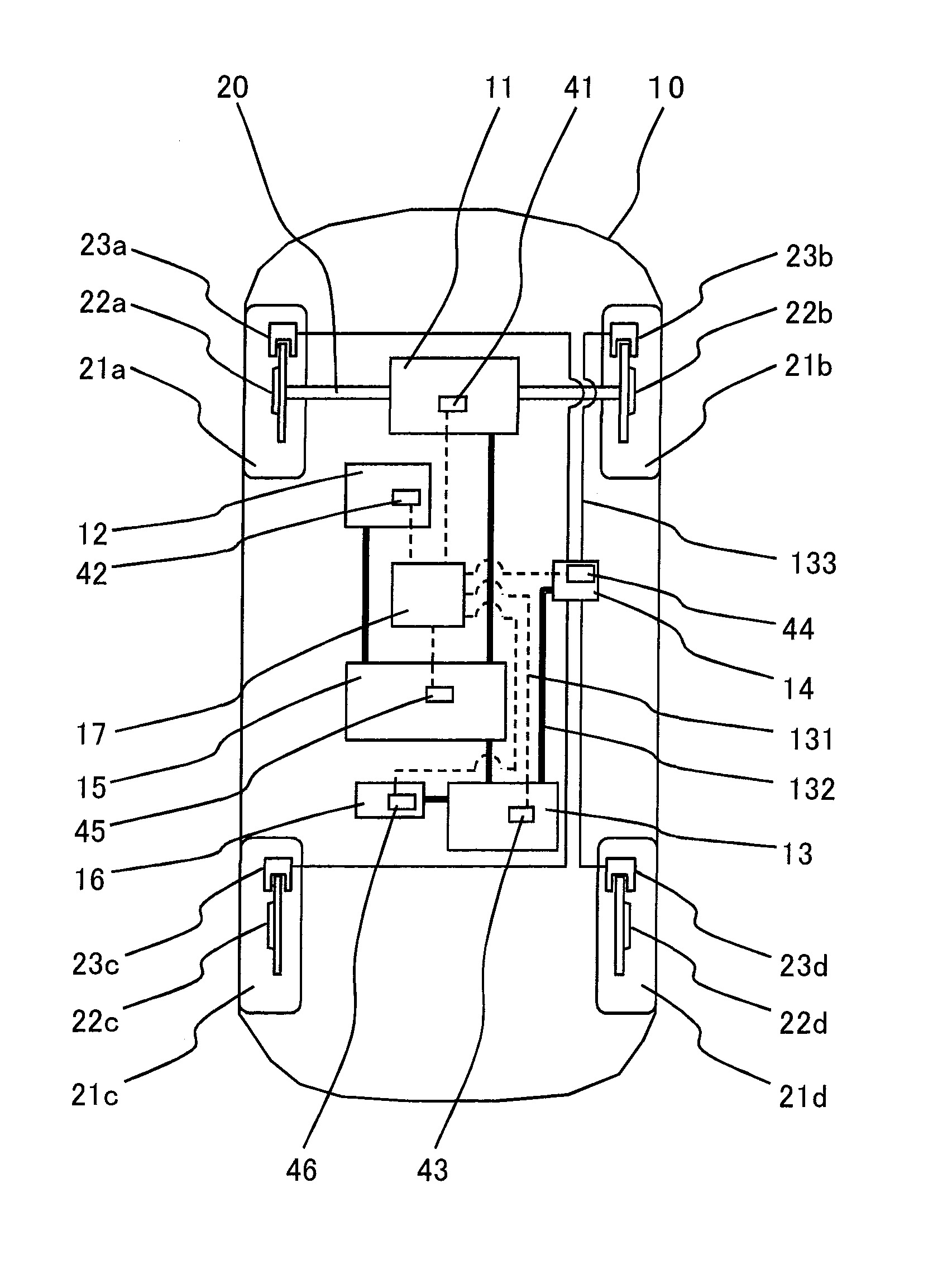
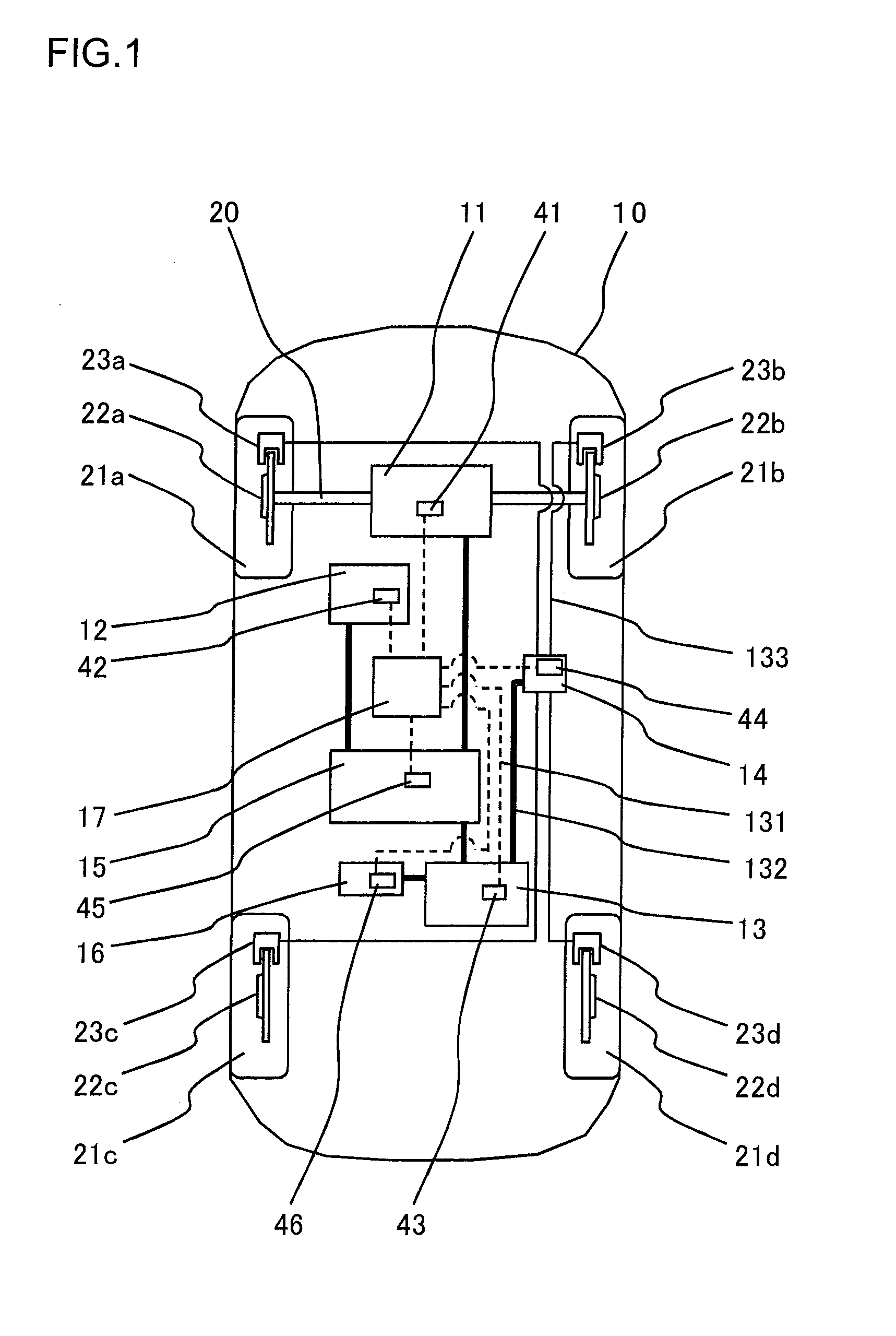
[0037]FIG. 1 shows the structure of an electric vehicle 10 to which a control system according to the first embodiment is mounted. This electric vehicle 10 according to the first embodiment includes a motor-generator (an electric machine) 11, a temperature regulation device 12, an electrical power conversion device...

embodiment 2

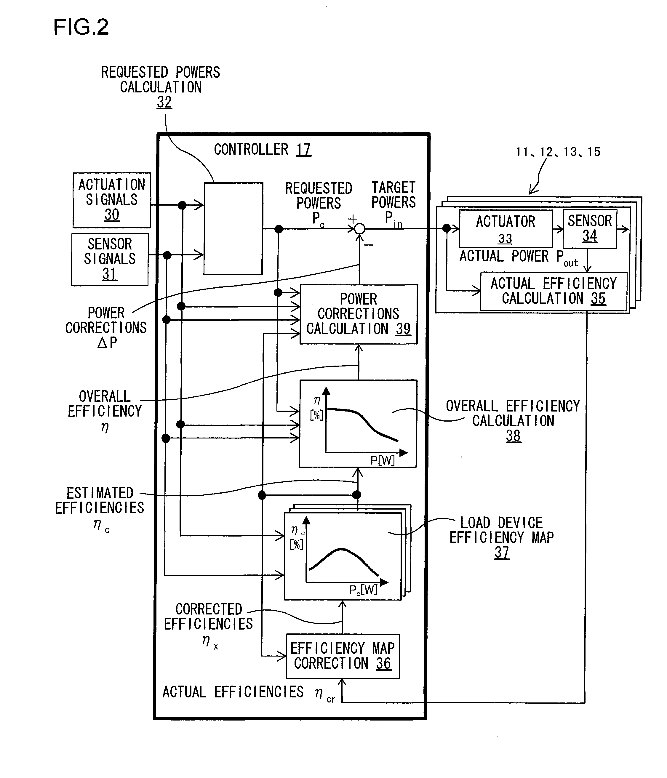
[0076]A second embodiment of the present invention will now be explained with reference to FIGS. 11 and 12. The control system of this second embodiment has a travel prediction unit 40 added to the control system of the first embodiment shown in FIG. 2; apart from this feature, this second embodiment is the same as the first embodiment shown in FIG. 2. It should be understood that it would also be acceptable to add a travel prediction unit 40 to the control system of the variant of the first embodiment shown in FIG. 3; with the present invention, the control system to which a travel prediction unit may be provided is not to be considered as being particularly limited.

[0077]At predetermined intervals, the travel prediction unit 40 inputs signals from the actuation signals 30 specifying the amounts of actuation by the driver of the accelerator pedal and the brake pedal, and the set temperature upon the temperature regulation device 12 and / or its set amount of air flow and so on, and a...

embodiment 3

[0082]A third embodiment of the present invention will now be explained with reference to FIG. 13. While in this third embodiment an example will be presented in which, as in the case of the first and second embodiments, the present invention is applied to an electric vehicle of the front wheel drive type, the present invention could also be applied to an electric vehicle of the rear wheel drive type or of the four wheel drive type, to a hybrid electric vehicle that is also provided with an internal combustion engine, or to an electric vehicle for construction, an electric vehicle for a railroad, or indeed an electric vehicle of any kind.

[0083]This electric vehicle 10 of the third embodiment is one in which a thermal storage device 18 has been added to the electric vehicle 10 of the first embodiment shown in FIG. 1; the other details thereof are the same as those of the electric vehicle 10 shown in FIG. 1.

[0084]This thermal storage device 18 is a device that is connected to the moto...


PUM


Abstract

A control system for an electric vehicle includes: an electricity storage device that performs charging and discharging of electrical power; a plurality of load devices that receive supply of electrical power from the electricity storage device and perform operations; and a control device that controls the electricity storage device and the plurality of load devices. And when electrical power is supplied from the electricity storage device to the plurality of load devices, the control device calculates a charge/discharge efficiency of the electricity storage device and a working efficiency of each of the load devices, and regulates an amount of electrical power supplied from the electricity storage device to each of the load devices, so as to enhance an overall efficiency of the electricity storage device and the plurality of load devices.

Description

INCORPORATION BY REFERENCE[0001]The disclosure of the following priority application is herein incorporated by reference: Japanese Patent Application No. 2009-262527 filed Nov. 18, 2009.BACKGROUND OF THE INVENTION[0002]1. Field of the Invention[0003]The present invention relates to a control system for an electric vehicle, and to an electric vehicle equipped with this control system.[0004]2. Description of Related Art[0005]A plurality of load devices such as one or more electricity storage devices, an electric motor and a temperature regulation device, an electrical power conversion device and so on are mounted to an electric vehicle, and control of these load devices is performed on the basis of command values such as the amount with which an accelerator pedal or a brake pedal is depressed by the driver, a temperature setting, and so on. With an electric vehicle, the greatest problem is to increase the range, and methods for increasing the range are, for example, to increase the am...

Claims


Application Information

Patent Timeline
IPC IPC(8): B60L15/20B60L50/10
CPCY02T10/7283B60L15/2045B60L2260/56B60L2200/26H02J7/0068B60L11/1861H02J7/0063Y02T10/72B60L1/003B60L1/02B60L2240/34B60L2240/425Y02T10/64Y02T10/70H02J7/007182B60L58/12
Inventor NASU, SHINGOYOKOYAMA, ATSUSHIOSAKA, TADASHISAWADA, ITSURO
Owner HITACHI LTD
Why Eureka
Try Eureka