Directly Driven Seed Meter Hub Drive

a technology of seed meter hub drive and drive shaft, which is applied in the direction of potato planters, gearing, centrifugal wheel fertilisers, etc., can solve the problems of inability to address the numerous issues associated with the operational uniformity the torque required to drive all of the seed metering system by a common main drive shaft can be significant, and achieve the effect of facilitating the transfer of force therebetween

Active Publication Date: 2011-05-26
BLUE LEAF I P INC
View PDF3 Cites 35 Cited by
  • Summary
  • Abstract
  • Description
  • Claims
  • Application Information

AI Technical Summary

Benefits of technology

[0011]In still further implementations, the direct drive mechanism interfaces with the outer circumferential surface of the seek disk and selectively rotates it. Such an interfacing relationship can be realized between the hub of the seek disk and a pinion gear driven by the prime mover. Accordingly, the outer circumferential surface of the seek disk hub and the outer circumferential surface of the output gear have corresponding structures which facilitate the transfer of force therebetween. As one example, the outer circumferential surfaces can have spur gear teeth, interfacing and meshing with each other. As another example, the outer circumferential surfaces can have helical gear teeth interfacing and meshing with each other.

Problems solved by technology

Although such previous perimeter drive units may improve compactness of seed metering systems to some extent, they fail to address numerous issues associated with operational uniformity of seed metering systems.
Known seed metering systems, concentric drive and perimeter drive alike, face various performance uniformity issues related to the operation of conventional main, common driveshaft and meter driveshaft linkages.
For example, the torque required to drive all of the seed metering systems by a common main driveshaft can be significant, since each seed metering system can experience high levels of friction during operation as, e.g. the vacuum force pulls the seek disk toward and into contact with the meter housing.
As another example, non-uniform operation can result from non-desired rotational drive speed variations realized at the meter driveshaft as the chains and / or cables flex, relax, tighten, and slacken as the row crop planter traverses somewhat irregular field surfaces.
Any of these and other operating characteristics can lead to erratic seed placement.
Additionally, typical seed planters do not have the ability to deactivate individual row planting units, independently of one another.
This can lead to overseeding or overplanting, dispensing more seed than needed, during various instances in which portions of the seed planter passes over a segment of the field more than once.
However, such efforts require the use of complex assemblies, for example, pneumatic clutch assemblies with numerous parts and which can require relatively large amounts of energy to operate.

Method used


Image

  • Directly Driven Seed Meter Hub Drive
  • Directly Driven Seed Meter Hub Drive
  • Directly Driven Seed Meter Hub Drive

Examples


Embodiment Construction

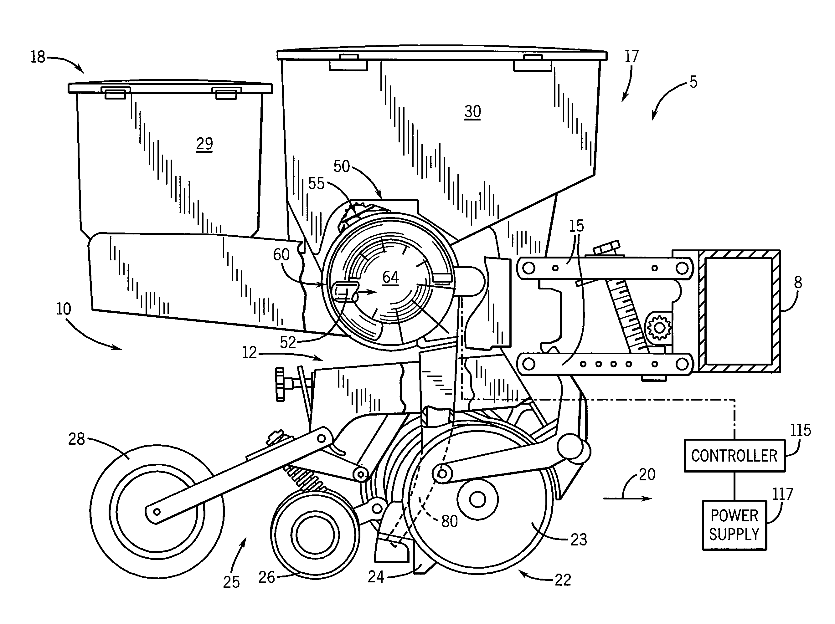
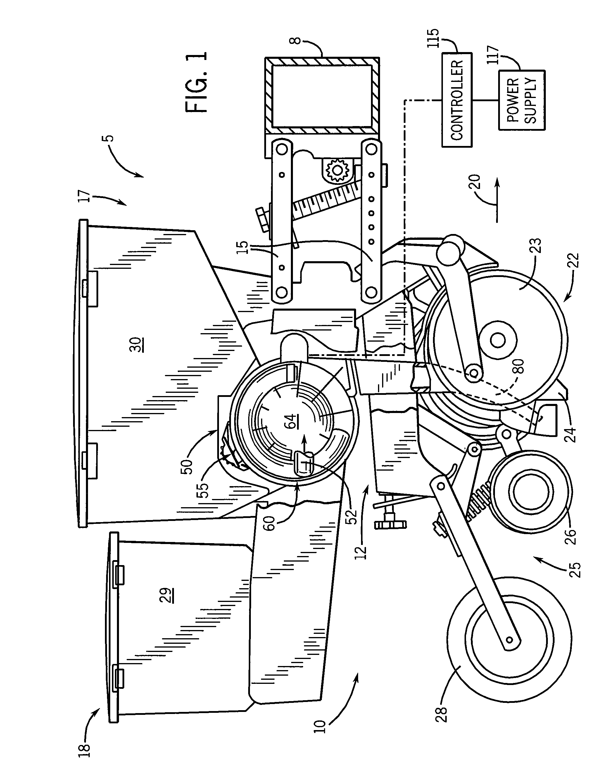
[0019]Referring now to the drawings and specifically to FIG. 1, a portion of a multiple row crop planter implement or seed planter 5 is shown. The seed planter 5 is typically pulled by a tractor or other traction device (not shown). Seed planter 5 includes a toolbar 8 that holds multiple individual row planting units 10, each row planting unit 10 being substantially identical. Only a single row planting unit 10 is shown for simplicity.

[0020]Row planting unit 10 includes a frame 12 that attaches the unit 10 to toolbar 8 by way of parallel linkages 15. Row planting unit 10 has a leading end 17 which faces the direction of travel, indicated by arrow 20. A trailing end 18 faces the opposite direction, away from the direction of travel 20. Frame 12 supports a furrow opening mechanism 22 near the leading end 17 of row planting unit 10, for cutting open the furrow to receive the deposited seeds. As is known in the art, the furrow opening mechanism 22 includes a pair of lateral spaced furro...


PUM


Abstract

A direct drive electric seed metering system is provided for use with a row crop planter or seed planter that intakes a volume of multiple seeds from a seed hopper, draws individual seeds from the volume of multiple seeds and discharges them into a seed furrow formed in an agricultural field. The direct drive electric seed metering system includes a meter assembly having a meter housing and a seek disk rotatably mounted concentrically in the housing for singulating the seeds. A direct drive mechanism is mounted to the meter assembly for interfacing and driving the seek disk at an angular velocity which corresponds to the travel velocity of the seed planter. A single seed planter can have multiple direct drive electric seed metering systems, and each of the multiple direct drive electric seed metering systems preferably has its own prime mover to effectuate driving the seek disk.

Description

BACKGROUND OF THE INVENTION[0001]The invention relates generally to seed planters for dispensing individual seeds at a controlled rate into a seed furrow, and in particular, to a device and corresponding method for metering seeds at a desired rate.[0002]Modern row crop planters or seed planters include multiple row planting units attached to a toolbar and towed behind a tractor. Each of the row planting units are responsible for opening a seed trench or furrow, dispensing the seeds into the furrow, then closing the furrow after the seeds are planted. The seed furrows are opened by a first pair of discs extending down from the planter at its leading end, closed by a second pair of discs extending down from the planter at its trailing end, and then tamped down by a trailing wheel which follows both disc pairs.[0003]Typically, each row planting unit has its own seed hopper and seed metering system for dispensing the seeds at a controlled rate into the seed trench or furrow as the plant...

Claims


Application Information

Patent Timeline
Patent Type & Authority Applications(United States)
IPC IPC(8): A01C7/08F16H35/00
CPCY10T74/19A01C19/02A01C7/046
Inventor WENDTE, KEITHADAMS, BRIAN
Owner BLUE LEAF I P INC
Why Eureka
Try Eureka