Eureka AIR delivers breakthrough ideas for toughest innovation challenges, trusted by R&D personnel around the world.

Exhaust Gas Recirculation Valve Actuator

Inactive Publication Date: 2011-05-26
ACTUANT CORP
View PDF15 Cites 8 Cited by
  • Summary
  • Abstract
  • Description
  • Claims
  • Application Information

AI Technical Summary

Benefits of technology

[0007]In some embodiments, the present invention provides an EGR system for an engine that includes an intake port in fluid communication with an intake manifold of the engine and an exhaust line in fluid communication with at least one exhaust manifold of the engine. The system also includes an exhaust gas recirculation conduit in fluid communication with the exhaust line and the intake port and a cooler fluidly positioned along the exhaust gas recirculation conduit and in fluid communication with the

Problems solved by technology

The valves that are used in EGR applications are subjected to extremely severe operating conditions, as they must operate over a large temperature range (typically −40° C.-800° C., sometimes up to 1000° C.) since the exhaust is extremely hot, and the exhaust contains corrosive and acidic materials.
Further still, the actuators used to control such valves typically do not have high accuracy.
In addition, only a low amount of force can be applied if the valve is directly controlled by a solenoid.

Method used


Image

  • Exhaust Gas Recirculation Valve Actuator
  • Exhaust Gas Recirculation Valve Actuator
  • Exhaust Gas Recirculation Valve Actuator

Examples


Embodiment Construction

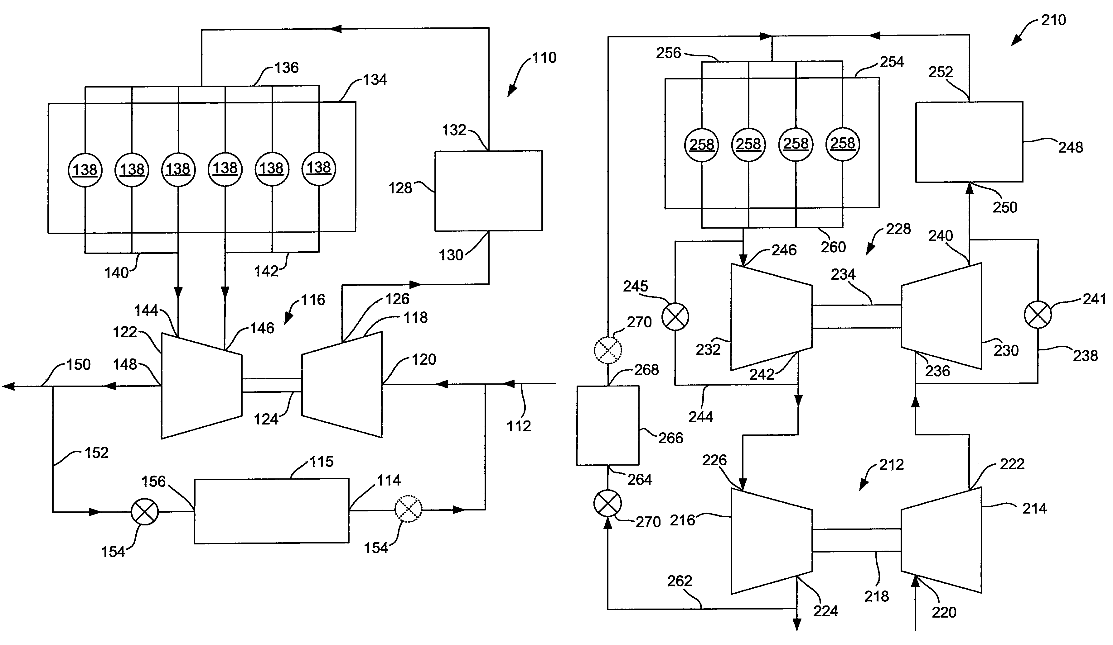
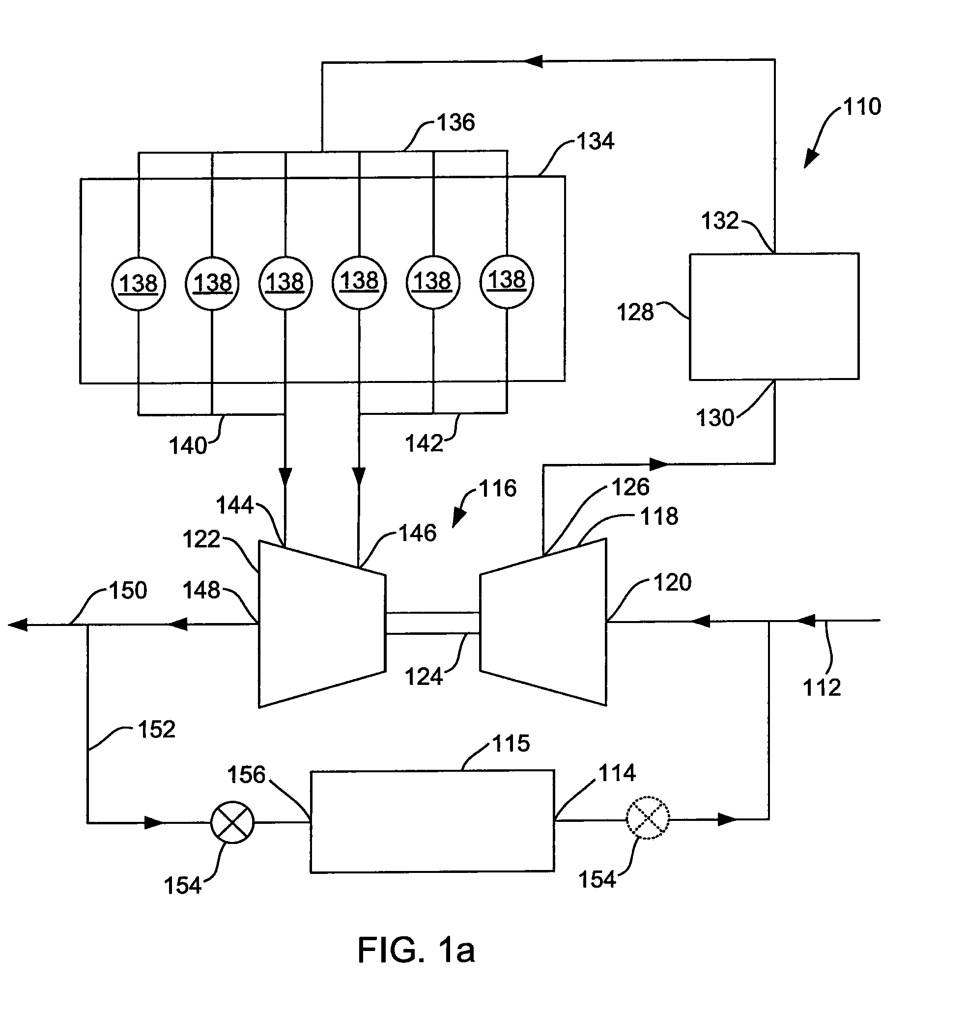
[0023]FIG. 1a shows a schematic representation of an exhaust gas recirculation (EGR) system 110. The system 110 includes an intake port 112 that may be in fluid communication with the air filter (not shown) of a vehicle. The intake port 112 fluidly communicates with an outlet 114 of a cooler 115. The cooler 115 may be any type of cooler commonly used in this type of system. The intake port 112 also fluidly communicates with a turbocharger 116. Specifically, the intake port 112 fluidly communicates with the inlet 120 of a compressor 118 of the turbocharger 116. The turbocharger 116 also includes a turbine 122 rotatably coupled to the compressor 118 by a shaft 124. An outlet 126 of the compressor 118 fluidly communicates with an inlet 130 of a cooler 128. The cooler 128 may be any type of cooler commonly used to cool gases from the compressor of a turbocharger. An outlet 132 of the cooler 128 fluidly communicates with the intake manifold 136 of an engine block 134. The engine block in...


PUM


Abstract

An EGR system for an engine that includes an exhaust gas recirculation conduit in fluid communication with an exhaust line and an intake port is provided. A cooler is fluidly positioned along the exhaust gas recirculation conduit and in fluid communication with the exhaust line and the intake port. A valve is fluidly positioned along the exhaust gas recirculation conduit and in fluid communication with the exhaust line and the intake port. The valve includes an electronic solenoid controlled hydraulic actuator operable to control the valve, and the actuator includes a position feedback sensor to detect a position of the valve.

Description

CROSS-REFERENCE TO RELATED APPLICATION[0001]This application claims the benefit of U.S. Provisional Patent Application No. 61 / 079,680 filed Jul. 10, 2008, the disclosure of which is hereby incorporated by reference in its entirety.STATEMENT CONCERNING FEDERALLY SPONSORED RESEARCH OR DEVELOPMENT[0002]Not applicable.FIELD OF THE INVENTION[0003]The present invention relates to valves for exhaust gas recirculation (EGR) systems, and in particular to such a valve that is a solenoid controlled valve.BACKGROUND OF THE INVENTION[0004]Exhaust gas recirculation (EGR) systems have become popular to assist vehicles in meeting emission requirements. EGR systems achieve this by diverting a portion or all of the exhaust gas back to the intake manifold of the engine. The gas is thereby combusted on multiple occasions before leaving the system. In addition, EGR systems can include a turbocharger to provide highly pressurized combustion gas to the engine.[0005]A valve is typically employed to control...

Claims


Application Information

Patent Timeline
IPC IPC(8): F02M25/07F01N13/00F02B37/00
CPCF02M25/0707F02M25/0756Y02T10/121F02M25/0793F02M25/0772F02B37/186F02D9/105F02D9/106F16K1/221F16K31/1635F02M26/05F02M26/08F02M26/23F02M26/48F02M26/53F02M26/59F02M26/70Y02T10/12
Inventor LILLY, DARYL A.
Owner ACTUANT CORP
Why Eureka
Eureka Blog
Learn More