Portable integrated laser optical target tracker

a laser and optical target technology, applied in the field of laser designating and spotting systems, can solve the problems of high cost, poor spot detection performance, and weight factor, and each piece of equipment requires separate maintenance, and achieves the effect of convenient field us

Inactive Publication Date: 2011-05-26
CISCO TECH INC +1
View PDF16 Cites 42 Cited by
  • Summary
  • Abstract
  • Description
  • Claims
  • Application Information

AI Technical Summary

Benefits of technology

[0007]Preferably, the PILOTT also includes inputs connected to the controller for GPS, for example from a defense advanced GPS receiver (DAGR). Alternatively, it is possible to integrate a GPS receiver in the PILOTT device. An input is also provided for thermal and / or night vision inputs from any thermal (MWIR and LWIR), SWIR, or night vision scope which can be connected to the housing. This decouples the thermal from the laser spot detector and makes the thermal only for situational awareness. These are overlaid with the optical field of view of the optical scope mounted in the housing so that the complete vision scene as well as all relevant data is displayed for easy observation by the user. This allows for easier use in the field. An optional internal SAASM GPS antenna and receiver may be added for use when a DAGR is unavailable.
[0008]Preferably, the PILOTT device is mounted on a stand having controllable actuators to adjust both the direction and tilt of the device for targeting purposes. This provides a stable platform in order to allow the PILOTT device to be used to designate a particular target with a laser beam emitted by the device at a selected frequency, the user to confirm the accuracy of the laser beam designation on the target via the optical field of view with the target location marked or indicated in the display, as well as also providing a GPS location of the target based on its range, compass heading and the GPS location of the device.

Problems solved by technology

Each of these pieces of equipment requires separate maintenance, and has a high cost, poor spot detection performance, and weight factor, which is of particular importance to field personnel carrying the equipment to a spotting site.

Method used


Image

  • Portable integrated laser optical target tracker
  • Portable integrated laser optical target tracker
  • Portable integrated laser optical target tracker

Examples


second embodiment

[0024]FIG. 18 is a front view of the PILOTT device shown in FIG. 11.

[0025]FIG. 19 is a view of a portable adjustable stand that is used to support the PILOTT device in use.

DETAILED DESCRIPTION OF THE PREFERRED EMBODIMENT(S)

[0026]Certain terminology is used in the following description for convenience only and is not considered limiting. The words “right,”“left,”“lower” and “upper” designate directions in the drawings to which reference is made. This terminology includes the words specifically noted above, derivatives thereof and words of similar import. A list of items indicated as “at least one of a, b or c” (where a, b and c represent the specific items referred to) means any one of a, b or c, or various combinations thereof. Additionally, the terms “a” and “one” are defined as including one or more of the referenced items unless specifically noted.

first embodiment

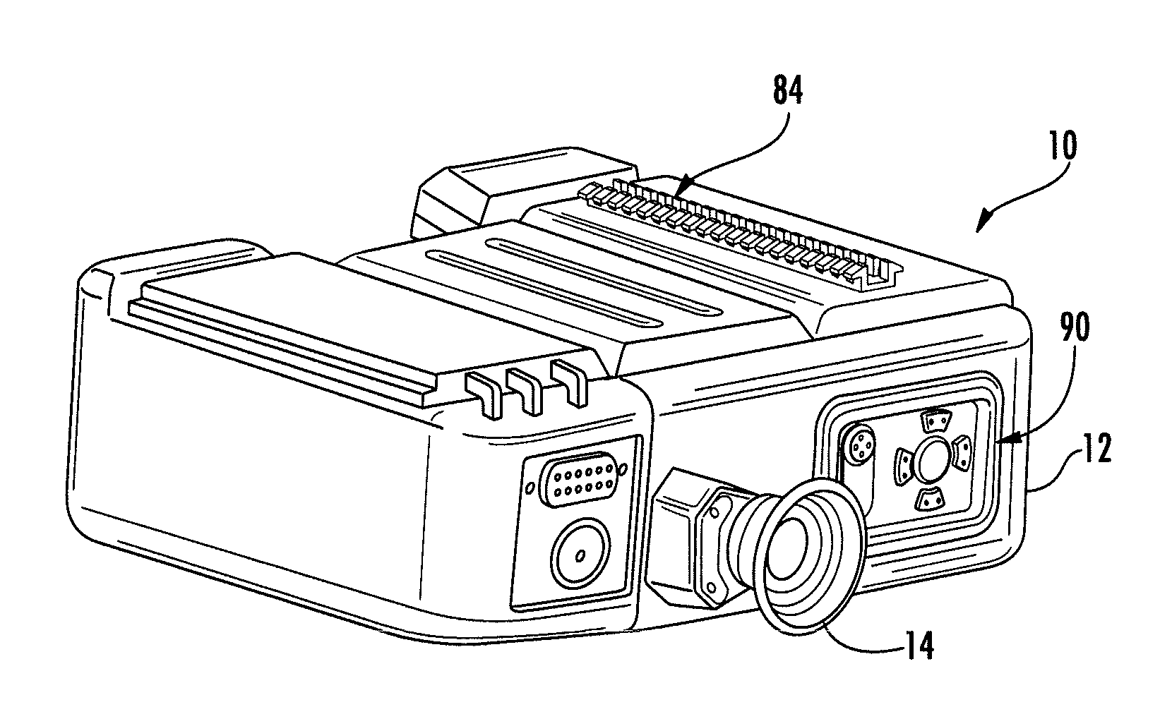
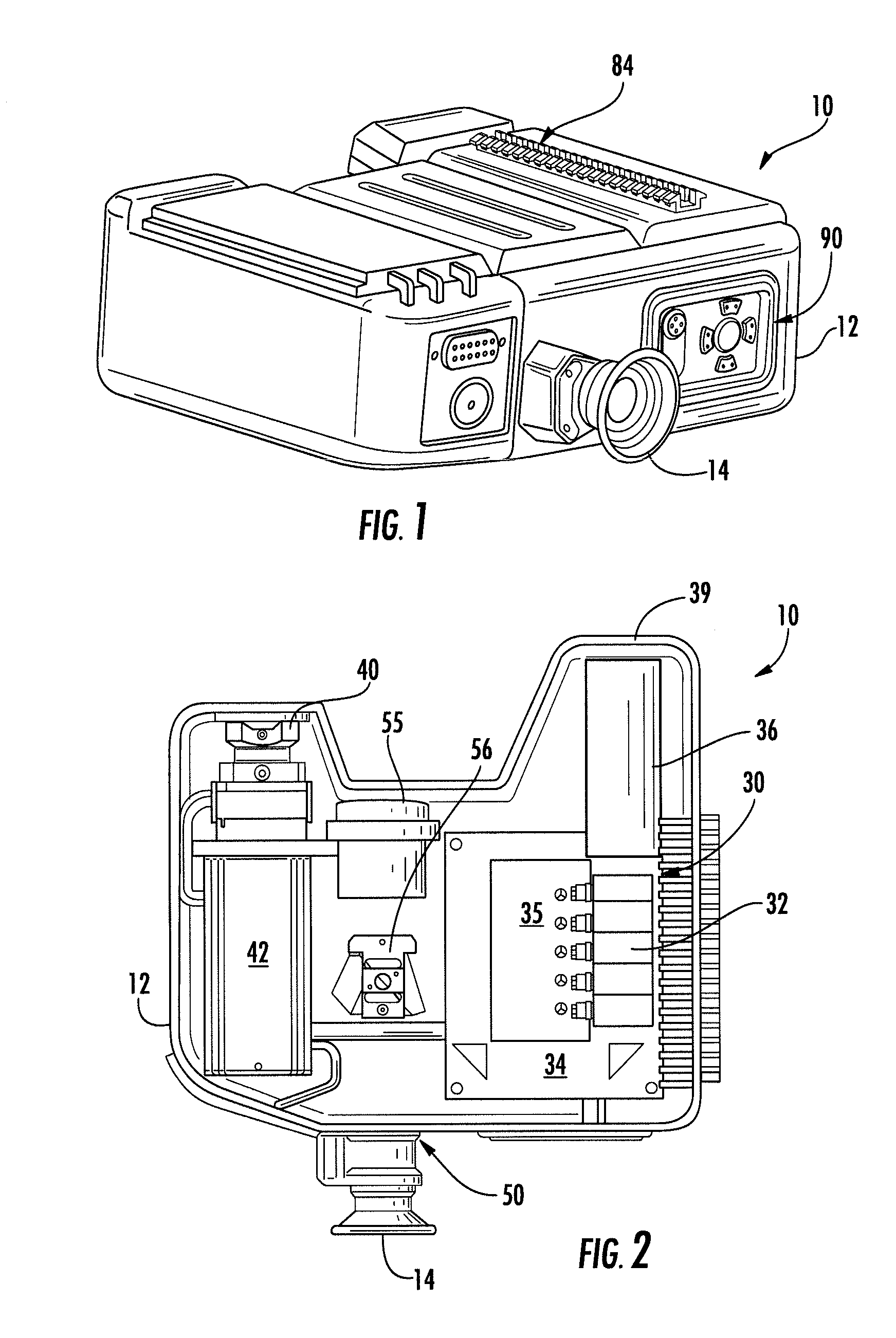
[0027]Referring to FIGS. 1-3, the PILOTT device 10 is shown. The PILOTT device 10 includes a housing 12, preferably formed as an upper half and a lower half, which are preferably formed of non-magnetic magnesium alloy. However, it can be made of other materials, such as machined or cast aluminum or any other suitable metal or polymeric material. The upper and lower housing halves are preferably sealed together in a water and moisture-proof manner.

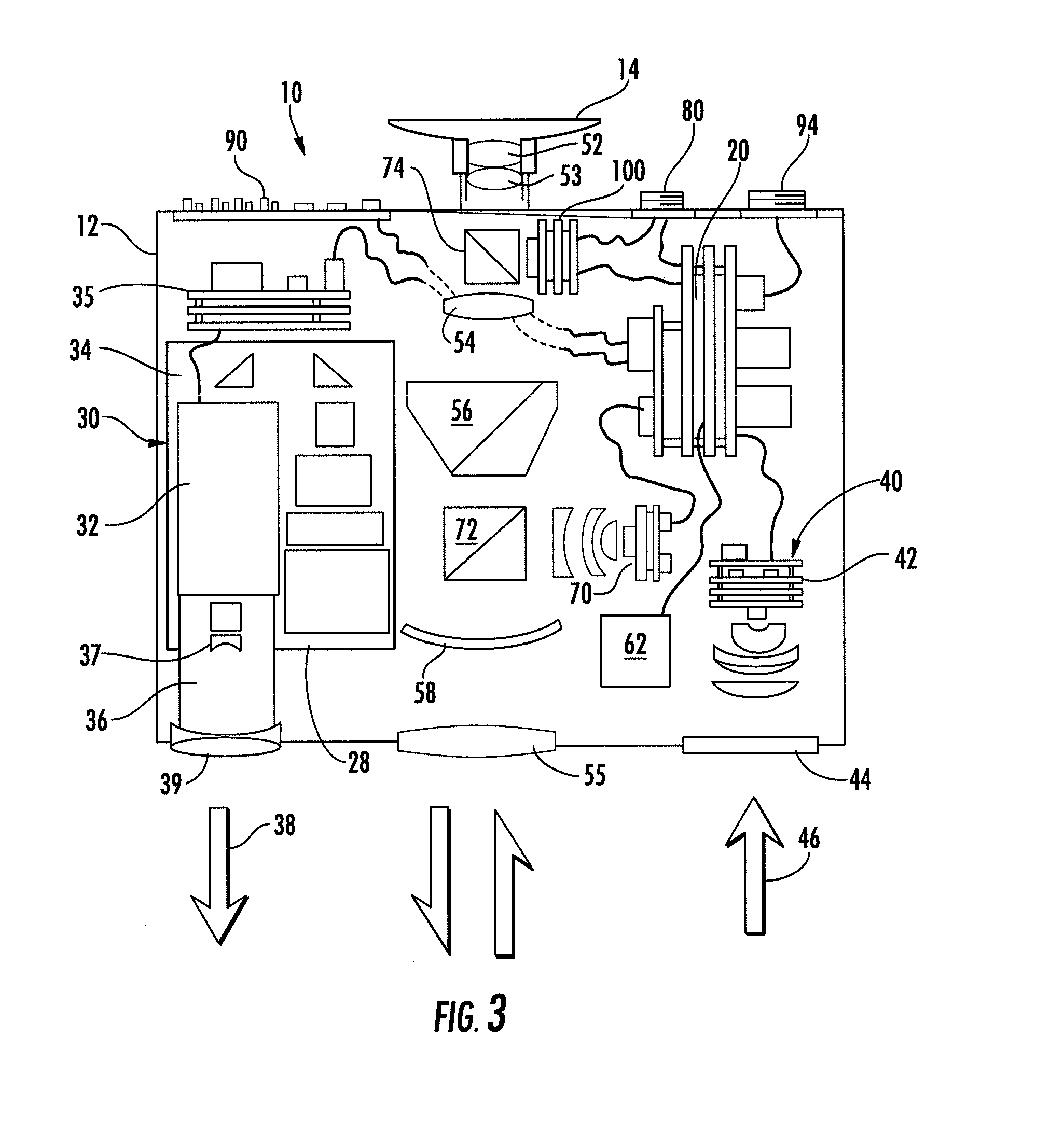
[0028]A laser designator assembly 30 is located within the housing 12. The laser designator assembly 30 includes a laser beam generator 32, which can be a diode-pumped solid state laser, or any other suitable high intensity laser generator. A laser controller 35 is used to control actuation of the laser and includes a frequency controller which pulses the laser beam 38 that is generated at a user input. The laser controller 35 is preferably a microprocessor, such as Microchip PIC24FJ256 GB106

[0029]Preferably, the laser is generated with a w...

example

LAT_Target(DD)=integervalueofdecimal=INT(decimal)LAT_Target(MM)=integervalueof[(decimal-DDvalue)*60]=INT((decimal-DD)*60)LAT_Target(SS)=[(decimal-DDvalue*60)-MM]*60[0099]Example

LAT_Target=40.208126degreesLAT-Target(DD)=INT(40.208126)=40LAT_Target(MM)=INT((40.208126-40)*60)=12LAT_Target(SS)=[((40.208126-40)*60)-12]*60=29.254LAT_Target=40°12′29.254″NLON_Target=75.078031degreesLON_Target(DD)=INT(75.078031)=75LON_Target(MM)=INT((75.078031-75)*60)=4LON_Target(SS)=[((75.078031-75)*60)-4]*60=40.912LON_Target=75°4′40.912″W

[0100]The user controls 90 are preferably as shown in FIG. 1, and include up, down, left and right arrow buttons along with an enter button which allows a user to scroll through the menu which appears on the electronic display 100. When the proper selection is highlighted, a user can either press enter, left or right in order to change selections. The main menu allows a user to select between the modes of operation, MARK, RANGE, TRACK or STANDBY as well as to set the displ...


PUM


Abstract

A portable integrated laser optical target tracker and designator (PILOTT device) in a single housing is provided having a laser designator assembly to produce a focused laser beam that is projected from the housing. A laser energy detector is located in the housing that detects reflected laser energy from any designation source (ground or airborne based), provides steering information, decodes the laser's frequency, and is used as a range finding receiver. The location of the laser energy provides automatic field alignment of the laser designator. An optical magnification scope is mounted in the housing and has an optical field of view that is parallel to and aligned with a beam path defined by the laser beam focusing optics. Any night scope can be added to the system to provide night situational awareness by being shown in the display. A visual electronic display is overlaid with the optical field of view. A main controller communicates with the controller of the laser energy detector and the visual electronic display, as well as a user input in order to control the PILOTT device. This allows the laser designation location to be displayed in the optical field of view, along with other data, for spotting, ranging and / or marking a designated target.

Description

CROSS-REFERENCE TO RELATED APPLICATIONS[0001]This application claims the benefit of U.S. Provisional Patent Application No. 61 / 263,560, filed Nov. 23, 2009, which is incorporated herein by reference as if fully set forth.FIELD OF INVENTION[0002]The invention relates to a laser designating and spotting system for targeting applications.BACKGROUND[0003]There are multiple military applications for laser designation and spotting systems. The currently known systems rely on a number of separate instruments for laser designating a target as well as for spotting and / or tracking a laser designation to ensure that the proper target has been acquired and marked. Generally, three to four separate pieces of equipment must be carried by a ground observer to a spotting and designating site within about six to eight kilometers of the target area in order to mark, range and / or track a target to be designated, and then relay information regarding the target to an ordinance delivery system or personn...

Claims


Application Information

Patent Timeline
Patent Type & Authority Applications(United States)
IPC IPC(8): G01S17/00G01S17/86
CPCF41G3/02F41G3/06G01S17/66G01S7/4813G01S17/023F41G3/145G01S17/86
Inventor MOURAR, EDWARD R.CARLO, MARIOSYRGABAEV, ILIAS
Owner CISCO TECH INC
Why Eureka
Try Eureka