Radiation detector

a detector and radiation technology, applied in the field of radiation detectors, can solve the problems of large number of frames of radiation image read-out per second (the frame rate), difficult to image video images of high frame rate, and speed of pixel read-out, so as to suppress differences in line capacitance and increase the speed of reading out pixels

Inactive Publication Date: 2011-05-26
FUJIFILM CORP
View PDF2 Cites 16 Cited by
  • Summary
  • Abstract
  • Description
  • Claims
  • Application Information

AI Technical Summary

Benefits of technology

[0036]Accordingly, the present invention can provide a radiation detector that can raise the speed of reading out the pixels and can suppress differences in line capacitance between signal lines.

Problems solved by technology

However, when radiation imaging apparatuses attempt to read out radiographic images successively from the radiation detector in order to obtain a video image, the number of frames of radiation image read-out per second (the frame rate) is large.
This makes it difficult to image video images of high frame rate.
Thus, although this technique may increase the speed of pixel read-out overall, they do not increase the speed of pixel read-out for a single pixel area.

Method used


Image

  • Radiation detector
  • Radiation detector
  • Radiation detector

Examples


first exemplary embodiment

[0058]As a first exemplary embodiment, a case in which the present invention is applied to an indirect-conversion-type of radiation detector 10A, which temporarily converts radiation to light and converts the converted light to charges, is described.

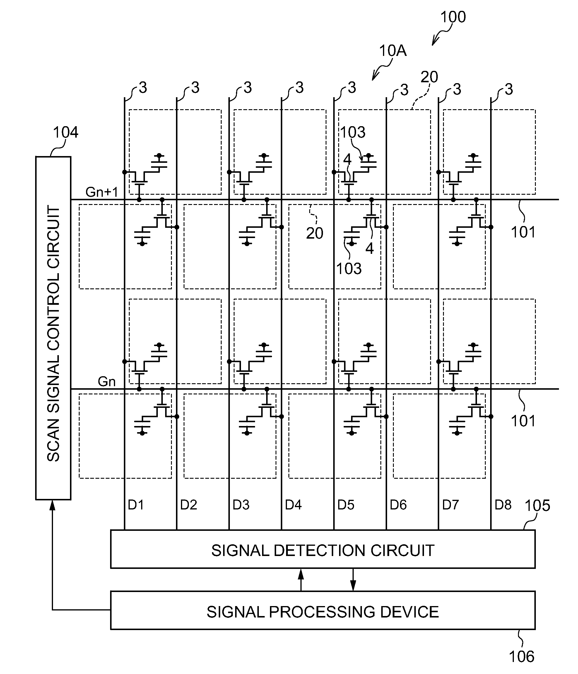
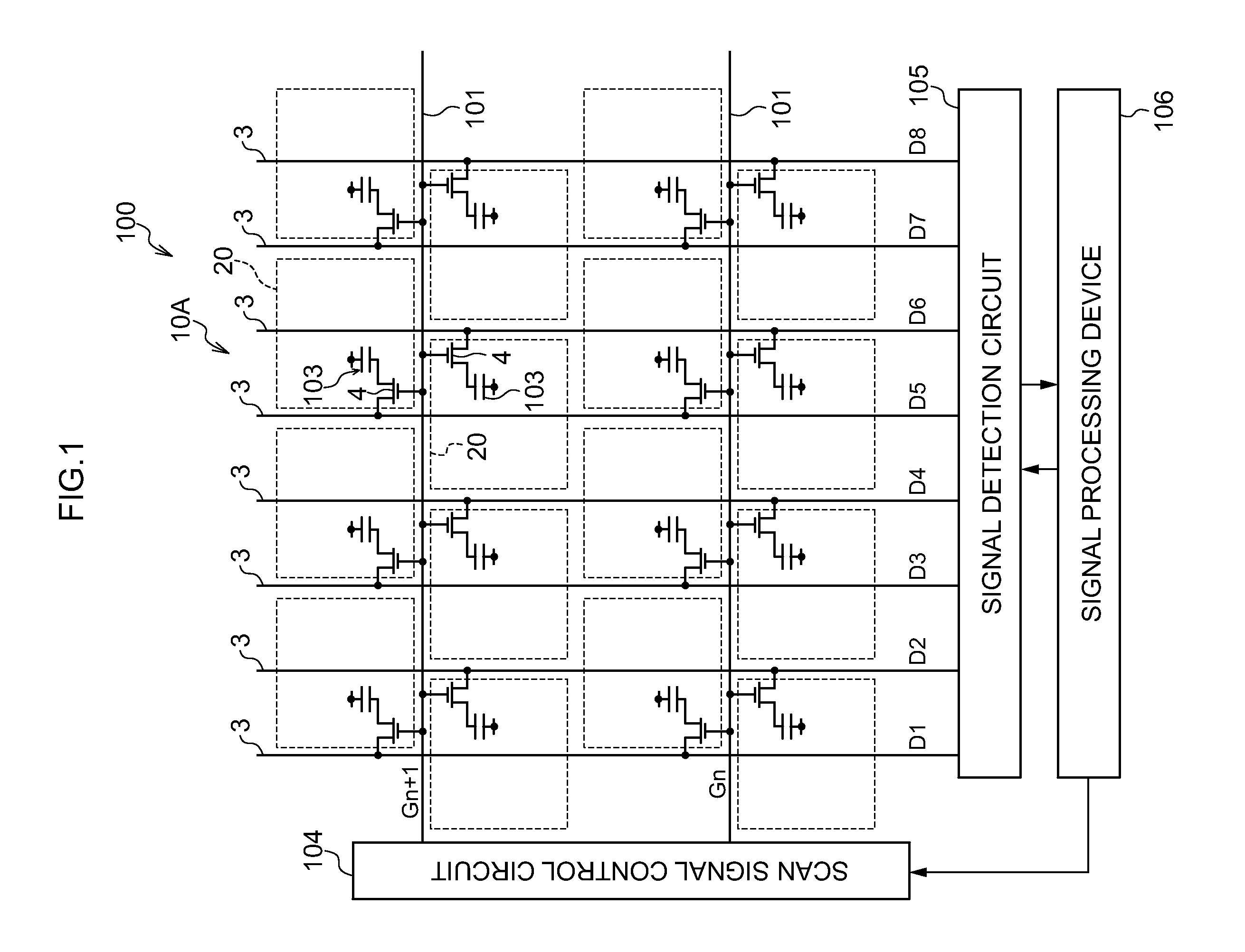
[0059]FIG. 1 illustrates the overall structure of a radiographic imaging device 100 that includes the radiation detector 10A according to the first exemplary embodiment.

[0060]As illustrated in FIG. 1, the radiographic imaging device 100 according to the present exemplary embodiment includes an indirect-conversion-type radiation detector 10A. Note that, a scintillator that converts radiation to light is not illustrated in FIG. 1.

[0061]The radiation detector 10A includes plural pixels 20 that are configured to include sensor portions 103 and TFT switches 4. The sensor portions 103 generate charges by illumination of light, and accumulate the generated charges. The TFT switches 4 read out the charges accumulated in the sensor portion 103.

[0...

second exemplary embodiment

[0094]Next, as a second exemplary embodiment, a case in which the present invention is applied to a direct-conversion-type of radiation detector, which converts radiation directly to charges, is described.

[0095]FIG. 4 illustrates the overall structure of the radiographic imaging device 100 that includes a radiation detector 10B according to the second exemplary embodiment. Herein, portions that correspond with the first exemplary embodiment described above (FIG. 1) are described with the same reference numerals as in the first exemplary embodiment.

[0096]In the radiation detector 10B, the plural pixels 20 are configured to include the sensor portions 103, the charge storage capacitors 5 and the TFT switches 4. The sensor portions 103 generate charges according to irradiation of radiation. The charge storage capacitors 5 accumulate the charges generated by the sensor portions 103. The TFT switches 4 read out the charges accumulated in the charge storage capacitors 5.

[0097]Similarly to...

third exemplary embodiment

[0121]Next, as a third exemplary embodiment, a case is described in which, in each pixel 20 of the direct conversion type radiation detector 10B, the TFT switch 4 and the charge storage capacitor 5 are separately disposed in two regions which are divided by the signal line 3 passing through a middle portion of the pixel 20.

[0122]FIG. 7 shows a plan view illustrating structure of the radiation detector 10B according to the present exemplary embodiment. Herein, portions that are the same as in the second exemplary embodiment (see FIG. 5) are assigned with same reference numerals and description thereof will be omitted.

[0123]As illustrated in FIG. 7, in the radiation detector 10B, the TFT switch 4 and charge storage capacitor 5 at each pixel 20 are disposed separately in two regions which are divided by the signal line 3 passing through the middle portion of the pixel 20.

[0124]FIG. 8 shows a cross-sectional diagram taken along A-A of FIG. 7. Portions that are the same as in the second ...


PUM


Abstract

Scan lines, each disposed to plural pixel lines for each of the pixel lines in a row direction of plural pixels disposed in a matrix, that switch each TFT switch provided at respective pixels in the plural pixel lines. Plural signal lines are each disposed to each of the pixel lines in the row direction of the matrix array. In each of the pixel lines in the row direction, respective signal line is connected to different TFT switch from the TFT switches that are connected to the same respective scan line, and charges accumulated in charge storage capacitors is read out according to the states of the TFT switches. The pixels or the signal lines at a subset of the pixel lines in one direction are disposed shifted in the one direction, such that the signal lines are disposed between pixels of the pixel lines.

Description

CROSS-REFERENCE TO RELATED APPLICATION[0001]This application claims priority under 35 USC 119 from Japanese Patent Application No. 2009-265196, filed on Nov. 20, 2009, the disclosure of which is incorporated by reference herein.BACKGROUND OF THE INVENTION[0002]1. Field of the Invention[0003]The present invention relates to a radiation detector. The present invention particularly relates to a radiation detector that accumulates charges generated by irradiation of radiation onto plural pixels disposed in a matrix, and that detects the accumulated charge amounts of the charges as information that represents an image.[0004]2. Description of the Related Art[0005]In recent years, radiation imaging devices using radiation detectors such as FPDs (flat panel detectors) in which x-ray sensitive layers are disposed on TFT (thin film transistor) active matrix substrates, and that can convert x-ray information directly to digital data, and the like, have been put into practice. As compared with ...

Claims


Application Information

Patent Timeline
Patent Type & Authority Applications(United States)
IPC IPC(8): G01T1/24
CPCH01L27/14663H04N5/32H04N5/378H04N5/376H04N5/37452H04N25/74H04N25/771H04N25/75
Inventor OKADA, YOSHIHIRO
Owner FUJIFILM CORP
Why Eureka
Try Eureka