This helps you quickly interpret patents by identifying the three key elements:
Problems solved by technology
Method used
Benefits of technology
Benefits of technology
[0032]According to the invention, the switch is inserted into the signal conductor for connecting the dipole antenna and the high-frequency circuit, and the antenna apparatus operates as a dipole antenna with no antenna current flowing into the feeder line at the first frequency and operates as a monopole antenna wherein the radiation element and the feeder line making up the dipole antenna becomes the radiation element at the second frequency lower than the first frequency.
[0033]Further, according to the invention, the first dipole antenna and the second dipole antenna are placed facing each other as mutual axial directions are orthogonal to each other on the same plane in which the board face is outwardly extended from the side of the one end-side of the board and in the perpendicular plane orthogonal to the board face and the one side-end and are placed so as to be inclined at an angle larger than 0 degrees and smaller than 90degrees with respect to the line parallel to the board face and ortho
Problems solved by technology
However, if a wireless system of a dual band and another wireless system are incorporated in one wireless communication apparatus, coupling caused by an antenna current flowing through a board occurs and it becomes impossible to conduct stable communications because of interference depending on the combination.
In the example described above, since the 1800 MHz band of GSM (1710 to 1880 MHz) is adjacent to the DECT band (1880 to 1900 MHz), if a monopole antenna is used as an antenna, interference occurs due to the antenna current flowing into the board and it becomes impossible to conduct stable communications.
Thus, if a highly convenient communication apparatus is configured using two wireless systems in combination, depending on the combination of the wireless systems, they interfere with each other and a problem arises in that the case where stable communications cannot be conducted occurs.
That is, if the DECT base unit is connected to the public telephone network using GSM, since DCS1800 and GSM have adjacent bands, when receiving a signal from a GSM base station, the GSM transmission-reception section of the DECT base unit also receives a transmission signal of the DECT base unit; conversely, when the DECT base unit receives a signal from a DECT cordlesshandset, the GSM transmission-reception section of the DECT base unit also receives a signal transmitted to a GSM base station, and a problem arises in that it becomes impossible to conduct mutually stable communications.
On the other hand, in recent years, it has become hard to sufficiently space installed antennas from each other with miniaturization of a wireless device and thus a new problem also arises in how isolation between the antennas is ensured in a limited space.
Method used
Image
Click on the blue label to locate the original text in one second.
Reading with bidirectional positioning of images and text.
Examples
embodiment 1
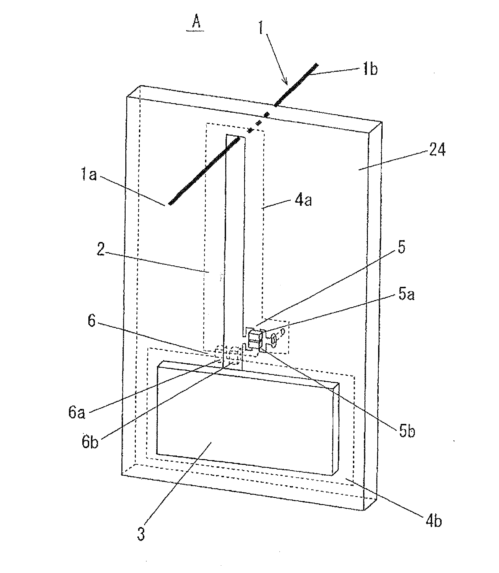
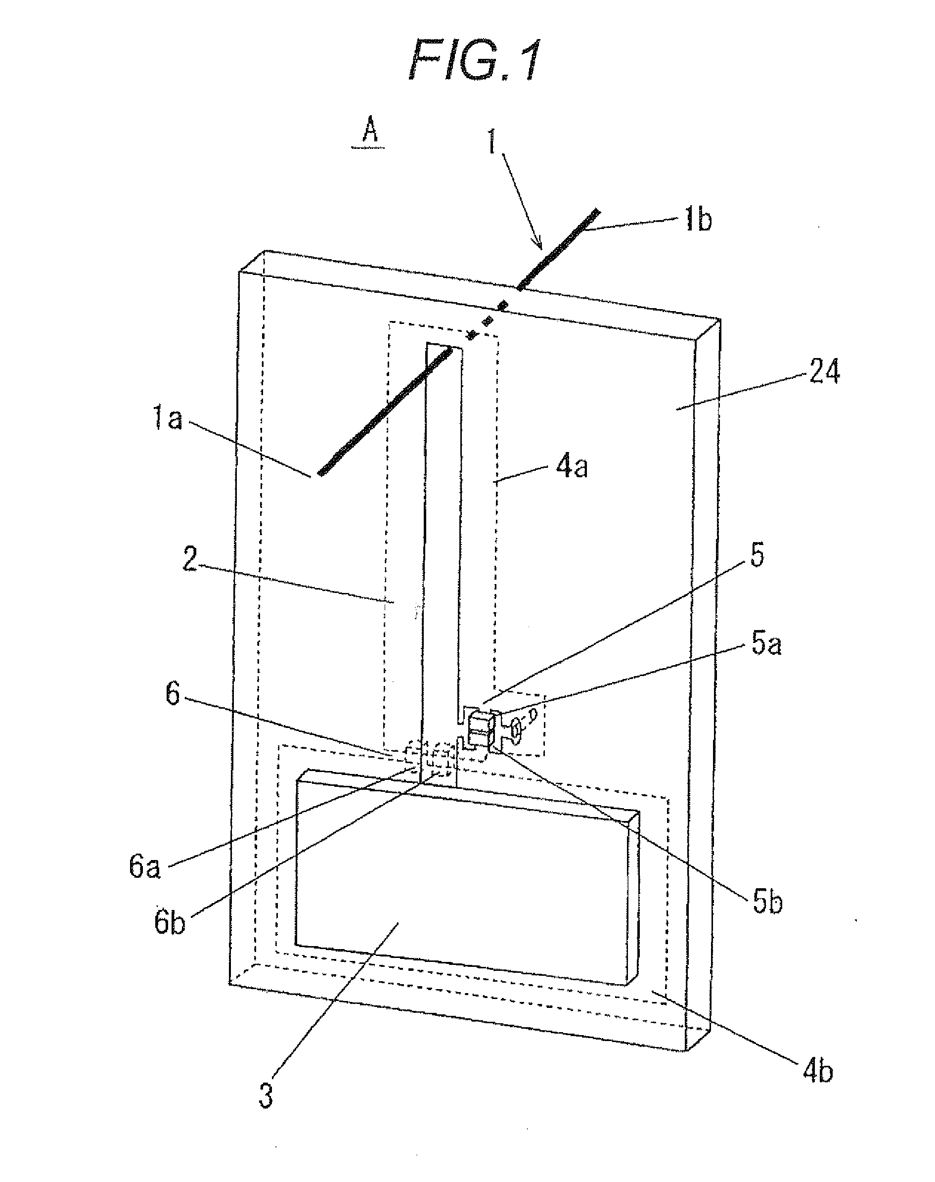
[0063]FIG. 1 is a perspective view to show the configuration of an antenna apparatus according to Embodiment 1. In FIG. 1, reference numeral 24 denotes a board. The direction parallel to the board face of the board 24 and orthogonal to left and right side-ends is the direction of a horizontal line. This means that the horizontal plane is a plane perpendicular to the board face of the board 24 and parallel to the top and bottom side-ends of the board 24. The direction parallel to the board face of the board 24 and orthogonal to the top and bottom side-ends is the direction of a vertical line. This means that the vertical plane is a plane perpendicular to the board face of the board 24 and parallel to the left and right side-ends of the board 24.
[0064](Configuration of Antenna Apparatus A)
[0065]As shown in FIG. 1, an antenna apparatus A according to Embodiment 1 includes a dipole antenna 1 placed on the side of one end (upper end in FIG. 1) of the board 24, a high-frequency module 3 o...
embodiment 2
[0098]FIG. 6 is a perspective view to show the configuration of an antenna apparatus according to Embodiment 2. Components identical with or equivalent to those shown in FIG. 1 (Embodiment 1) are denoted by the same reference numerals in FIG. 6. The description to follow centers on parts relating to Embodiment 2.
[0099](Characteristic Configuration of Antenna Apparatus B According to Embodiment 2)
[0100]As shown in FIG. 6, an antenna apparatus B according to Embodiment 2 has first and second switches 20 and 21 placed on the dipole antenna 1 side in place of the first and second switches 5 and 6 in the configuration shown in FIG. 1 (Embodiment 1).
[0101]In accordance with that, ground conductors 4a and 4b formed on the back of a board 24 are also changed. That is, the ground conductor 4a is formed on the periphery of the connection end part of a feeder line (signal conductor) 2 with a dipole antenna 1 and the ground conductor 4a is formed in the area corresponding to the most of the fee...
embodiment 3
[0122]FIG. 8 is a perspective view to show the configuration of an antenna apparatus according to Embodiment 3. Components identical with or equivalent to those shown in FIG. 1 (Embodiment 1) are denoted by the same reference numerals in FIG. 8. The description to follow centers on parts relating to Embodiment 3.
[0123](Characteristic Configuration of Antenna Apparatus C According to Embodiment 3)
[0124]As shown in FIG. 8, an antenna apparatus C according to Embodiment 3 is provided with a feeder line 25 bent at the right angle in place of the linear feeder line 2 in the configuration shown in FIG. 1 (Embodiment 1).
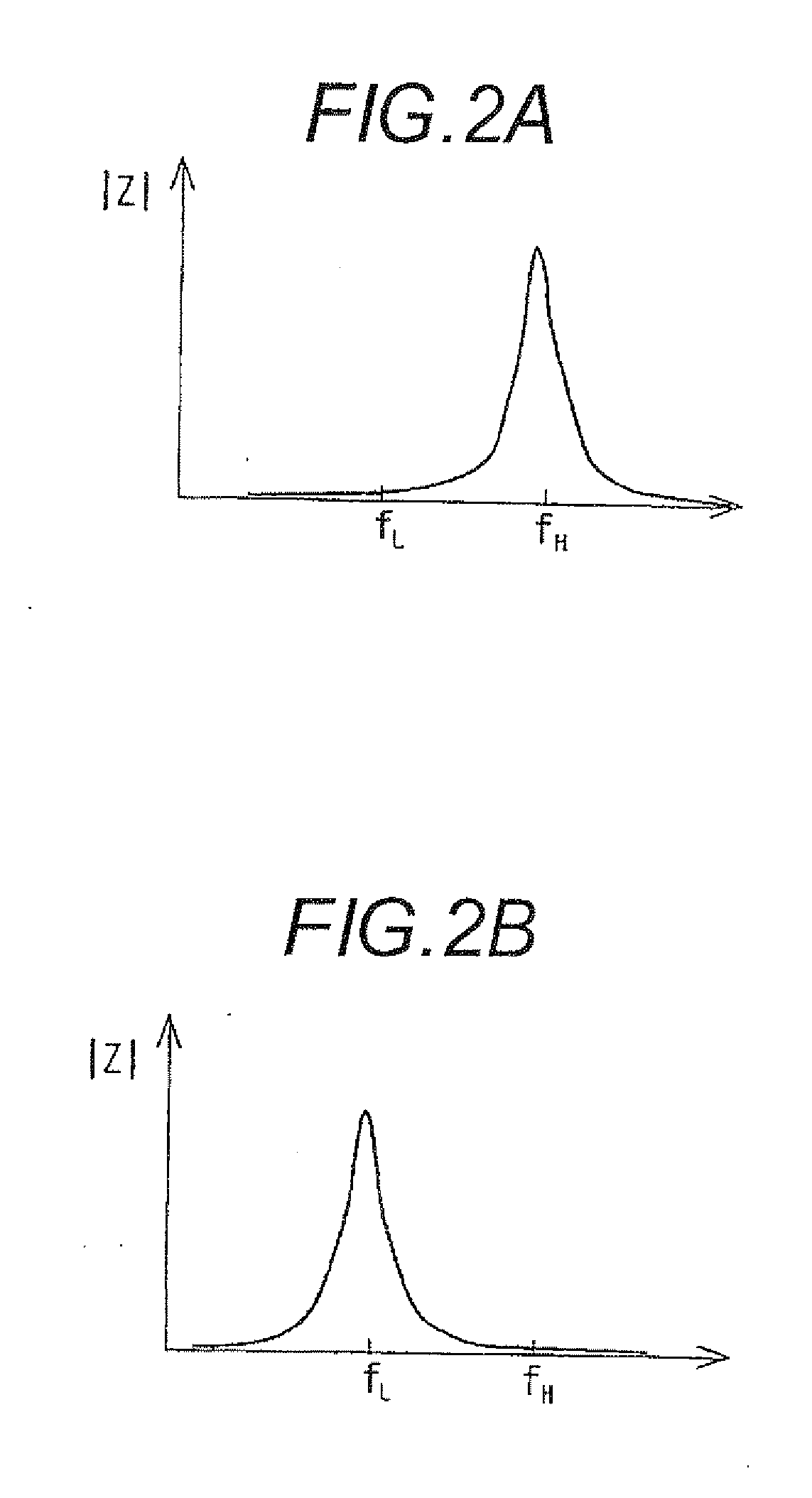
[0125]According to the configuration, the antenna apparatus operates as an inverted L antenna at a low-band frequency fL, so that it is made possible to decrease the height of the antenna apparatus.
[0126]While the application example to Embodiment 1 has been shown, the antenna apparatus of Embodiment 3 can also be applied to Embodiment 2 in a similar manner. The feeder line...
PUM
Abstract
An antenna apparatus that can be miniaturized without causing inference caused by antenna currents to be occurred if the high band of a dual band wirelesssystem is close to the band of another wirelesssystem in a wireless communication apparatus incorporating the dual band wireless system and another wireless system is provided. A first switch 5 blocks passage of a signal of a high band (first frequency) and allows passage of a signal of a low band (second frequency). A second switch 6 blocks passage of a signal of the low band (second frequency) and allows passage of a signal of the high band (first frequency). Accordingly, the antenna apparatus operates as a dipole antenna with no antenna current flowing into a feeder line at the first frequency and operates as a monopole antenna wherein a radiation element and a feeder line making up the dipole antenna becomes a radiation element at the second frequency lower than the first frequency.
Description
TECHNICAL FIELD[0001]This invention relates to an antenna apparatus, and in particular to an antenna apparatus used with a dual band wireless system in a wireless communication apparatus incorporating the dual band wireless system and another wireless system.[0002]The invention further relates to an antenna apparatus used with a communication apparatus installing a plurality of wireless devices thereon, and in particular to an antenna apparatus preferably used with a communication apparatus requiring antenna-to-antenna isolation.BACKGROUND ART[0003]In recent years, the number of wireless communication apparatus that can handle a wireless system of a dual band using two frequency bands of a high band and a low band as typified by a mobile telephone has increased. Among the wireless communication apparatus, to enhance convenience, a wireless communication apparatus incorporating another wireless system such as a wireless LAN also makes its appearance.[0004]As an example, a wireless co...
Claims
Application Information
Patent Timeline
Application Date:The date an application was filed.
Publication Date:The date a patent or application was officially published.
First Publication Date:The earliest publication date of a patent with the same application number.
Issue Date:Publication date of the patent grant document.
PCT Entry Date:The Entry date of PCT National Phase.
Estimated Expiry Date:The statutory expiry date of a patent right according to the Patent Law, and it is the longest term of protection that the patent right can achieve without the termination of the patent right due to other reasons(Term extension factor has been taken into account ).
Invalid Date:Actual expiry date is based on effective date or publication date of legal transaction data of invalid patent.

