
Oxygen to expand burner combustion capability

a technology of oxygen and burner combustion, which is applied in the direction of combustion using lumps and pulverulent fuels, combustion types, lighting and heating apparatuses, etc., can solve the problems of increasing maintenance, increasing emissions, and increasing so as to achieve stable combustion and reduce the risk of combustion failur

Inactive Publication Date: 2011-05-26
PRAXAIR TECH INC
View PDF13 Cites 1 Cited by
  • Summary
  • Abstract
  • Description
  • Claims
  • Application Information

AI Technical Summary

Benefits of technology

The present invention provides a method for modifying the operation of a burner by feeding air mixed with particulate solid carbonaceous fuel and other air streams through a burner. The fuel must meet certain conditions to maintain a stable flame, such as a certain mass flow rate, fuel-to-air ratio, and content of combustible matter. The method also involves feeding a stream of gaseous oxidant containing more than 21% oxygen to the burner to support the flame. This method allows for stable flame without the need for additional fuel and can be used with a variety of fuels.

Problems solved by technology

Attempts to combust fuel having one or more characteristics outside the range for that characteristic might encounter equipment limitations that prevent the system from reaching design capacity or might lead to negative side effects resulting in operational problems, higher emissions and increased maintenance.
Maintaining this minimum air flow rate thus dilutes the air / fuel mixture, under conditions of low fuel mass flow rates, to a degree that stable combustion can not be attained and the burner flame gradually extinguishes.
Fuels that contain more inert matter than the range of inert matter for which the combustion system is designed, and fuels that have a specific energy value below the range of specific energy values for which the system is designed, when fed into the combustion system, cause many of the problems such as inability to maintain combustion with a stable flame.

Method used


Image

  • Oxygen to expand burner combustion capability
  • Oxygen to expand burner combustion capability
  • Oxygen to expand burner combustion capability

Examples


Embodiment Construction

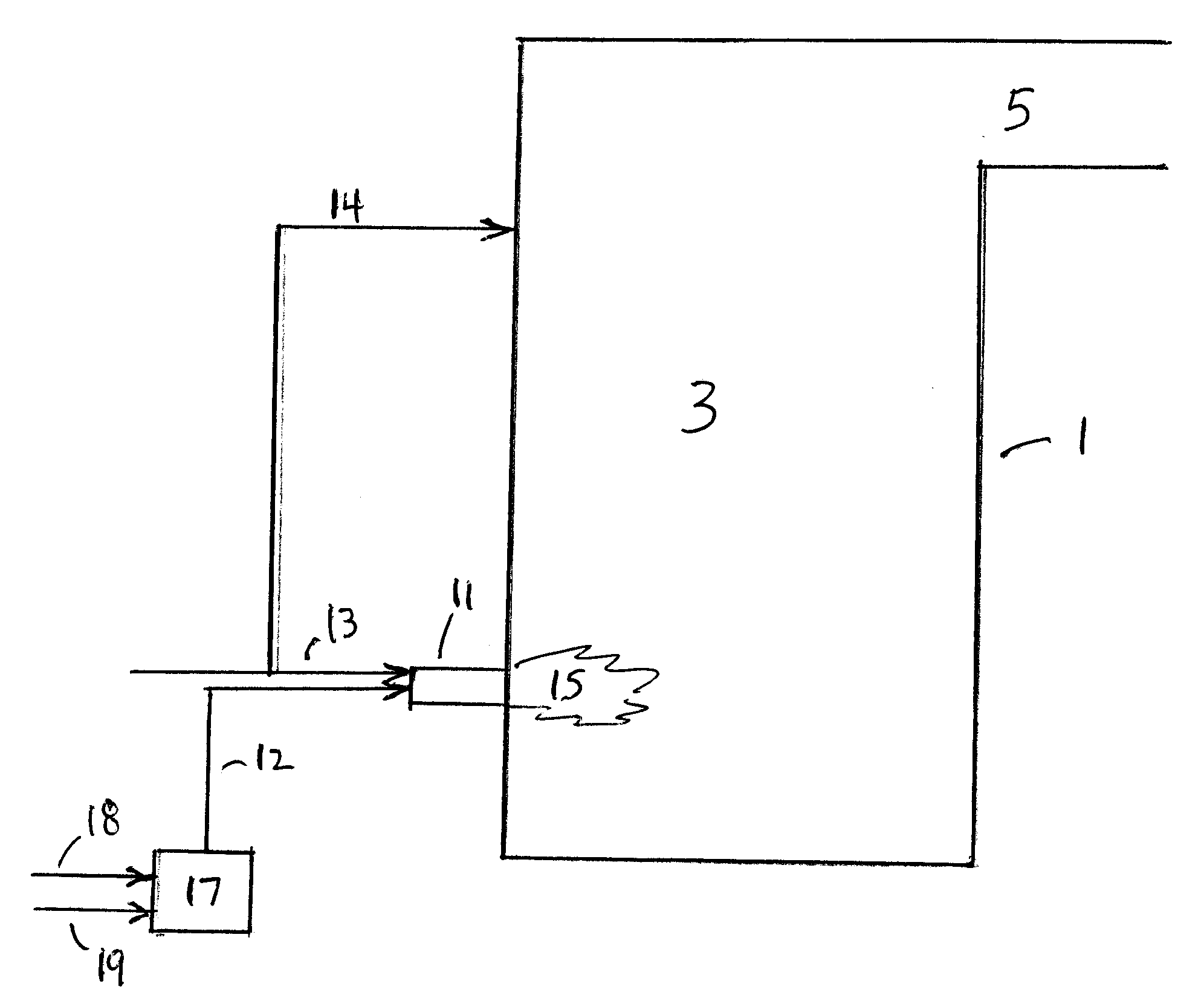
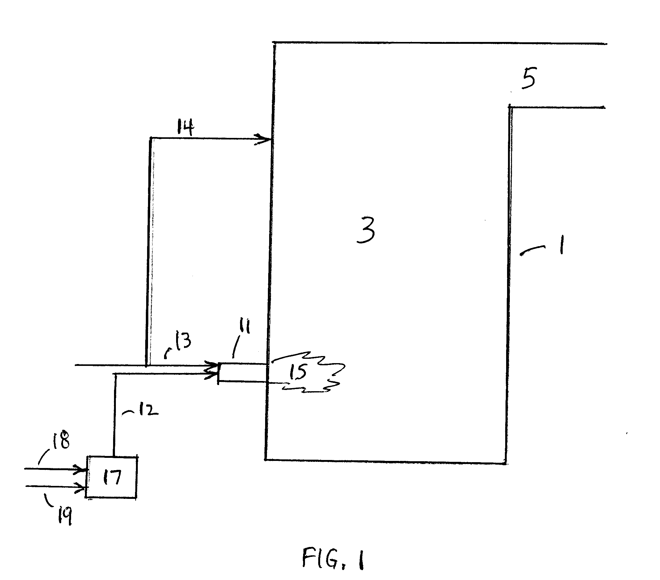
[0024]FIG. 1 depicts a representative combustion system with which the present invention can be practiced. The system includes combustion device 1, such as a coal-fired boiler. The fuel in this illustration is coal, but fuels with which the present invention is useful include any matter that has heating value, i.e. that liberates heat upon combustion. The terms “fuel” and “fuel solids” used herein refer to the matter that is fed to be combusted, including the combustible constituents thereof as well as any noncombustible constituents that are present.

[0025]Combustion device 1 houses combustion chamber 3, which is typically a space that can withstand the high temperatures that are attained by the combustion that is carried out in combustion chamber 3. The combustion chamber can be made of, or be lined with, refractory material, or it can be contained by walls of tubes that carry material such as water that absorbs heat from the combustion chamber. Products of the combustion pass out ...


PUM


Abstract

A burner at which fuel cannot be combusted with air as the only source of oxygen for combustion in a stable flame at the burner when the feed rate of the fuel is too low, when the fuel is fed at too high an air-to-fuel mass ratio, when the fuel contains too high an amount of inert matter, or when the specific energy content of the fuel is too low, is modified by supplying oxidant containing more than 21 vol. % oxygen into the base of a flame at the burner, whereupon such fuels can be combusted at the burner.

Description

[0001]This application is a continuation of, and claims priority from, application Ser. No. 11 / 475,026, filed Jun. 27, 2006.FIELD OF THE INVENTION[0002]The present invention relates to combustion of carbonaceous fuel in a combustion device such as a coal-fired utility boiler.BACKGROUND OF THE INVENTION[0003]Combustion systems are usually designed to burn fuel that is characterized in that one or more properties of the fuel relevant to combustion of the fuel lies within a range of values. The combustion system generally performs at its highest efficiency when the fuel characteristics fall within the ranges for which the system is designed. Attempts to combust fuel having one or more characteristics outside the range for that characteristic might encounter equipment limitations that prevent the system from reaching design capacity or might lead to negative side effects resulting in operational problems, higher emissions and increased maintenance. Features that may be affected by attem...

Claims


Application Information

Patent Timeline
Patent Type & Authority Applications(United States)
IPC IPC(8): F23D1/00
CPCF23D1/00F23D1/005Y02E20/344F23L7/007Y02E20/34
Inventor LAUX, STEFAN E.F.
Owner PRAXAIR TECH INC
Learn More