High density electrical connector

Active Publication Date: 2011-05-26
HON HAI PRECISION IND CO LTD
View PDF15 Cites 2 Cited by
  • Summary
  • Abstract
  • Description
  • Claims
  • Application Information

AI Technical Summary

Benefits of technology

[0006]An object of the present invention is to provide an

Problems solved by technology

The spring portion is located between the retaining portion and the solder portion which can not increase the flexibility evide

Method used


Image

  • High density electrical connector
  • High density electrical connector
  • High density electrical connector

Examples


Example

[0015]Reference will be made to the drawing figures to describe the present invention in detail, wherein depicted elements are not necessarily shown to scale and wherein like of similar elements are designated by same or similar reference numeral through the several views and same or similar terminology.

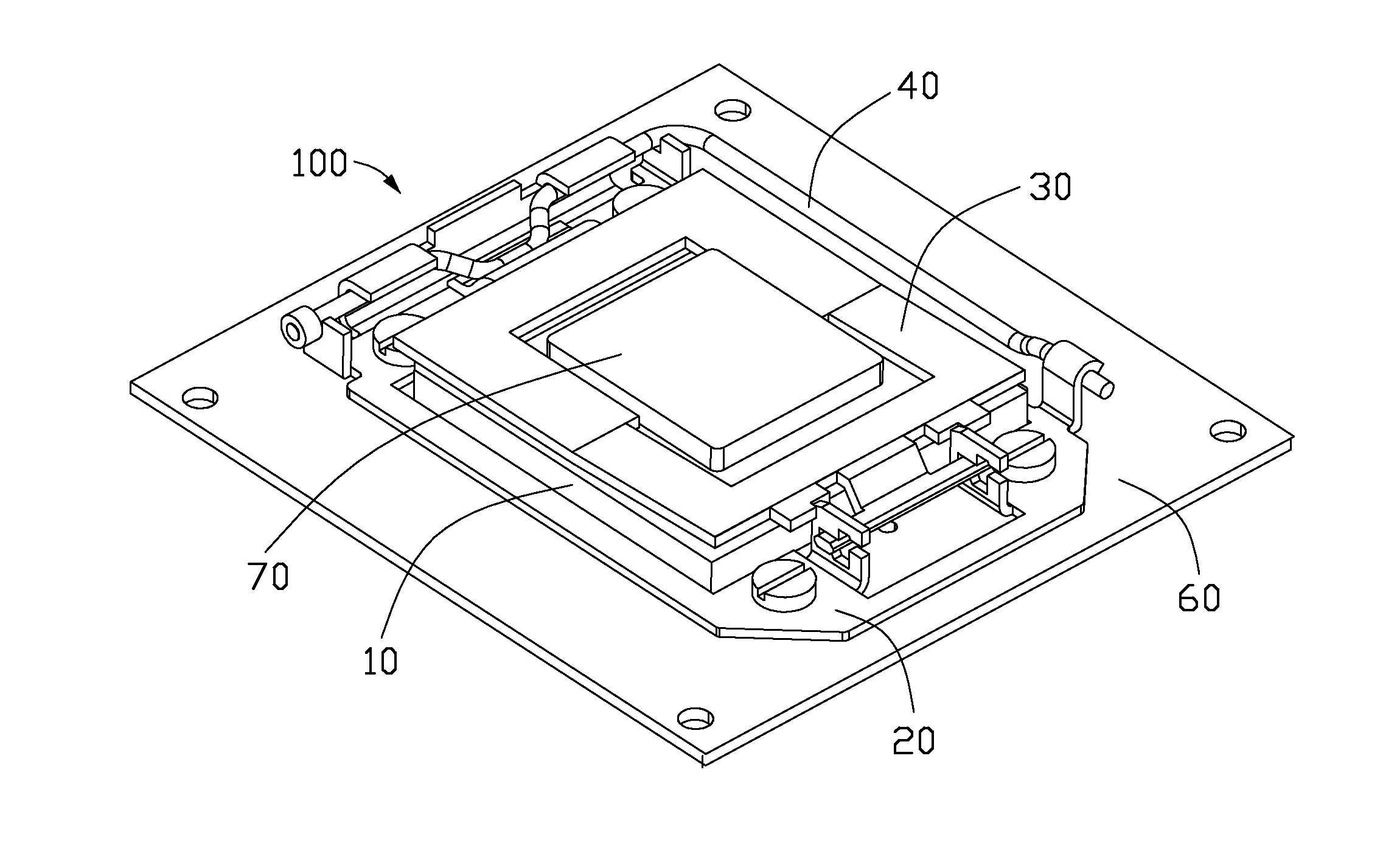
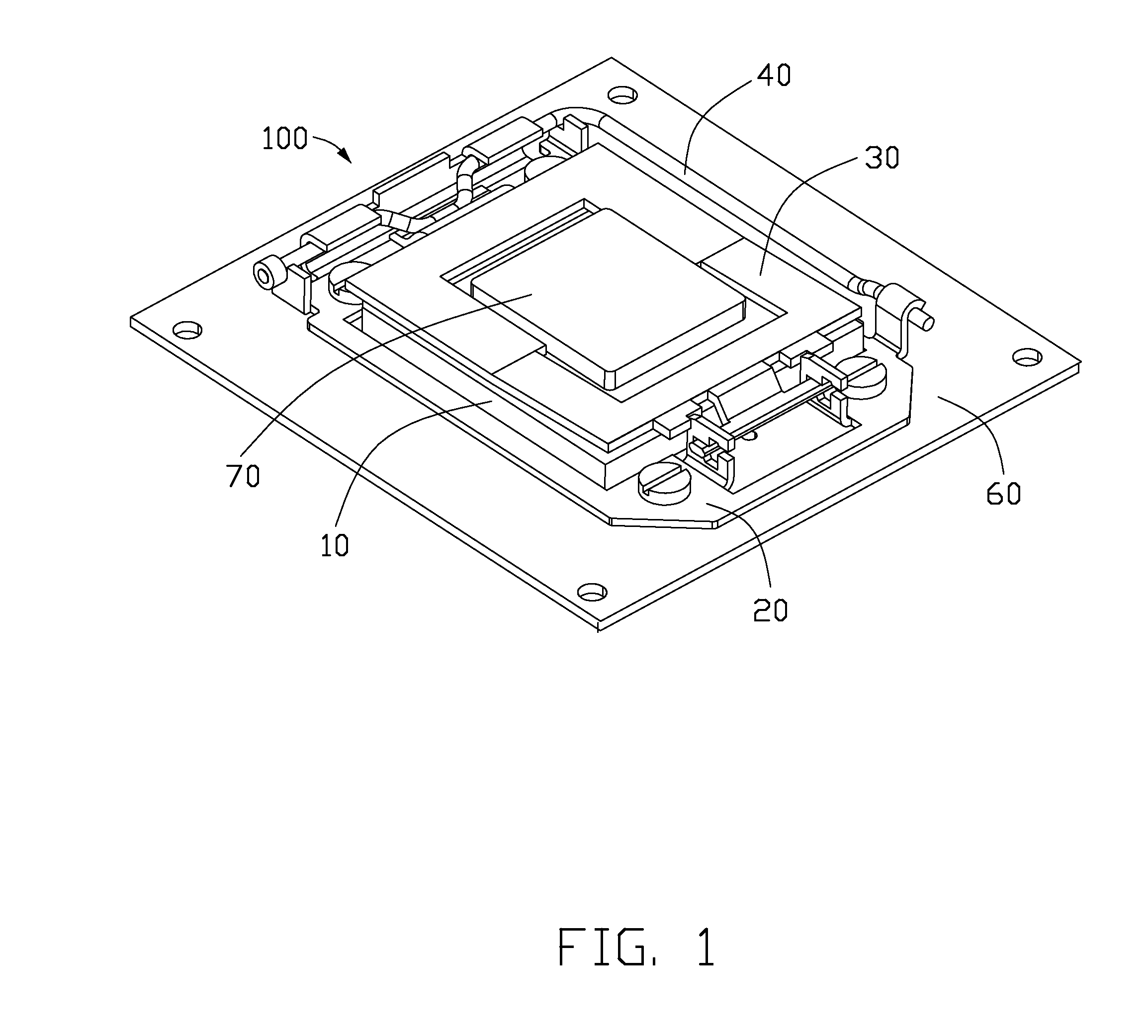
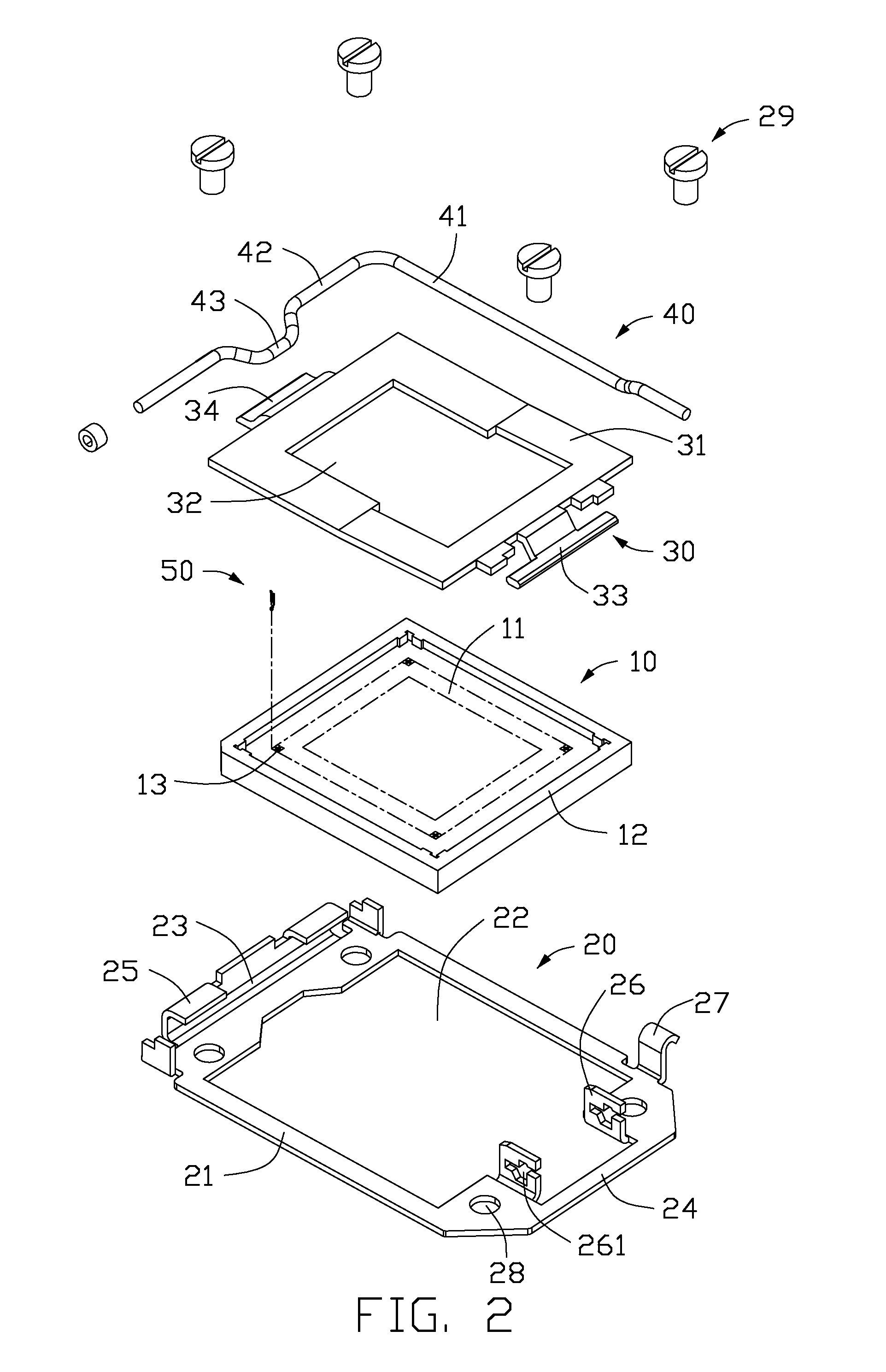
[0016]Please referring to FIGS. 1-2, the electrical connector 100 according to a preferred embodiment of the present invention is used to electrical connect a package 70 with a printed circuit board 60 and comprises an insulative housing 10, a plurality of electrical contacts 50 secured to the insulative housing 10, a stiffener 20 located at outer side of the insulative housing 10, a load plate 30 rotatably mounted to one end of the stiffener 20, and a load lever 40 rotatably mounted to the other end of the stiffener 20. The load plate 30 is used to press the package 70 on the insulative housing 10 and secured to the stiffen 20 by the load lever 40.

[0017]With reference to FIG. 2, the...


PUM


Abstract

An electrical connector includes an insulative housing and a number of electrical contacts secured to the insulative housing. Each of the contacts includes a flat plate engaging with the insulative housing, a spring arm bending and extending upwardly from a side edge of the flat plate and a solder tail extending downwardly from a lower portion of the flat plate. The spring arm has a first vertical portion connected with the body plate, an arc portion bending and extending upwardly from the first vertical portion, and a contact portion at a free end of the spring arm. Said arc portion and contact portion are located at same side of the first vertical portion.

Description

BACKGROUND OF THE INVENTION[0001]1. Field of the Invention[0002]The present invention relates to an electrical connector, and more particularly to an electrical connector mounted on a printed circuit board.[0003]2. Description of Related Art[0004]China patent application publication No. CN1953277A discloses an electrical connector mounted to a printed circuit board and electrical connected with a process package. The electrical connector includes an insulative housing with a plurality of passageways and a plurality of electrical contacts attached to the passageways of the insulative housing, respectively. The contacts each has retaining portion engaging with the passageway, a contacting portion extending upwardly from the retaining portion, a spring portion extending from lower end of the retaining portion, and a horizontal solder portion for soldering on the printed circuit board. The spring portion is bent from the retaining portion and used to enhance flexibility of the electrica...

Claims


Application Information

Patent Timeline
IPC IPC(8): H01R24/00
CPCH01R12/57H05K7/1069H01R13/2442
Inventor LIAO, FANG-JWUYEH, HUNG-YANG
Owner HON HAI PRECISION IND CO LTD
Why Eureka
Try Eureka