
Upgradable lattice tower and components thereof

a technology of lattice towers and components, applied in the direction of towers, antennas, buildings, etc., can solve the problems of inability to construct towers that can support unknown additional loads, inability to predict the future expansion of a network, and huge differences in the cost of towers

Inactive Publication Date: 2011-06-02
HEDINGER JOHAN +1
View PDF24 Cites 11 Cited by
  • Summary
  • Abstract
  • Description
  • Claims
  • Application Information

AI Technical Summary

Benefits of technology

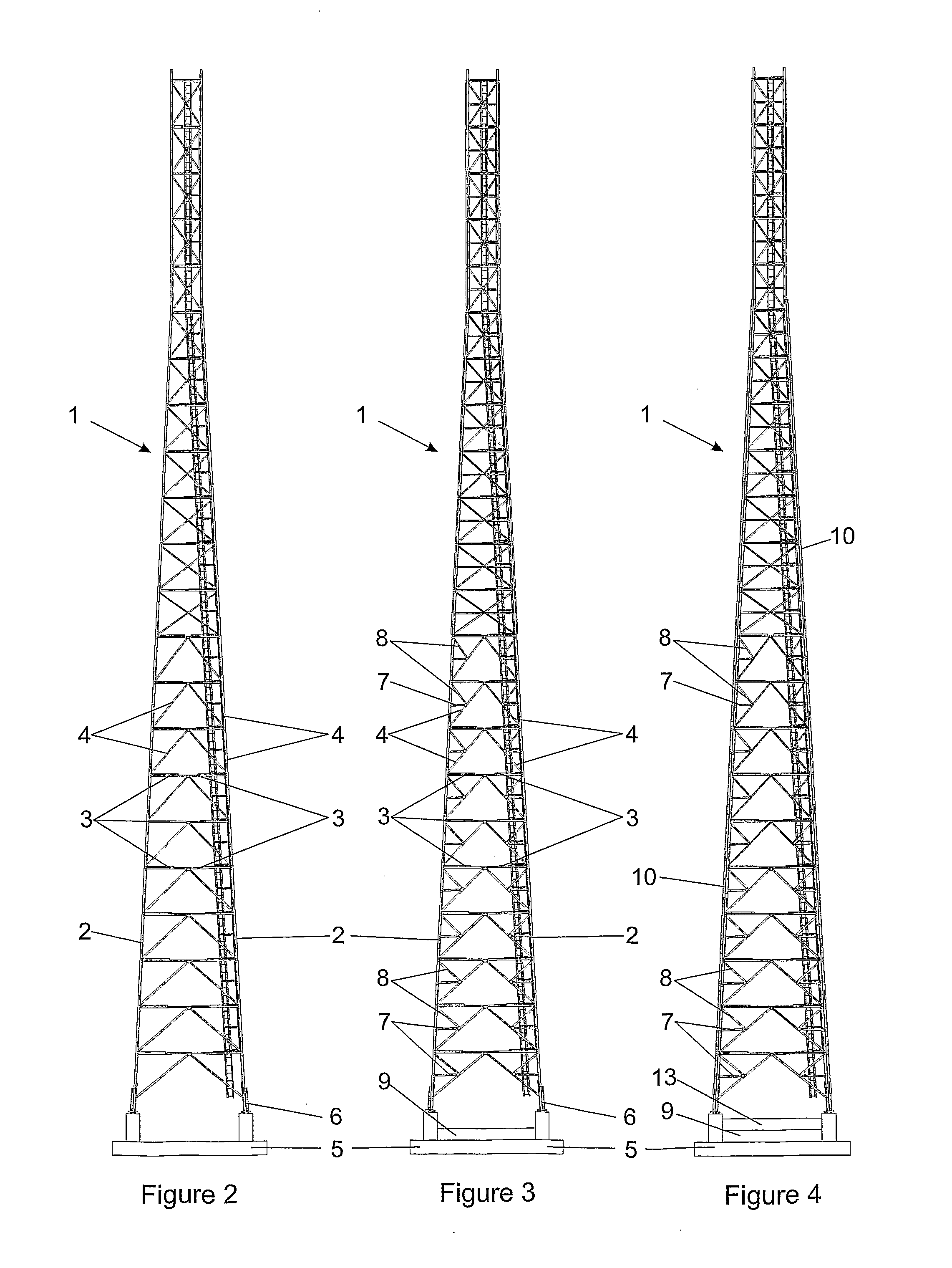
[0013]An upgrade may be achieved by the introduction of additional struts and additional diagonal braces that have the effect of reducing, typically halving, the span or buckling length of the basic components. An upgrade may also be achieved through doubling up of predetermined leg elements, predetermined horizontal struts and diagonal braces using parallel offset additional leg elements, additional horizontal struts and additional diagonal braces.

Problems solved by technology

Tower structures used to support wireless transmission equipment are designed to carry predetermined loads, and for reasons of cost, it is not generally practical to construct towers that can support unknown additional loads at a later date.
Even if future expansion is taken into consideration a network operator normally opts for the tower that best meets current requirements as future expansion of a network is extremely difficult to predict and there is an enormous difference in the cost of a tower, for example with a load bearing capacity corresponding to 20 square metres of antenna, when compared to one with a capacity corresponding to 30 square metres of antenna.
Accordingly, when the time comes to add additional equipment that exceeds the capacity of a tower, the network owner is faced with a number of difficulties.
New permits and re-zoning involve additional expenses and the time necessary for obtaining such new permits is often unpredictable.
In addition, there is the inevitable downtime that is required to disassemble one tower and assemble its successor, such downtime having tremendous financial implications and resulting in considerable inconvenience to the customer.
In applicant's view this proposal is likely to be costly; needs to be individually designed and fabricated to custom requirements for each tower structure at the time the necessity for reinforcing the structure arises; and provides unpredictable results in terms of the increased load capacity of the tower.

Method used


Image

  • Upgradable lattice tower and components thereof
  • Upgradable lattice tower and components thereof
  • Upgradable lattice tower and components thereof

Examples


Embodiment Construction

[0043]Before proceeding with a detailed description of the embodiments of the invention illustrated in the drawings, it is to be noted that upgrades as envisaged by this invention do not need to take place in complete upgrades as will be described in the example and each upgrade could take place in phases according to the increased load carrying capacity to be achieved. Thus, for example, a small increase in load carrying capacity could be achieved by upgrading using only some additional diagonal braces and possibly some additional horizontal struts that effectively halve the bending length of the relevant existing diagonal braces, horizontal struts and leg elements.

[0044]On the other hand, larger increases in carrying capacity may require doubling up of some or all of the horizontal struts and some or all of the leg elements. Each permutation and combination of components of a lattice tower that need to be introduced or upgraded by doubling their configuration can be planned in adv...


PUM


Abstract

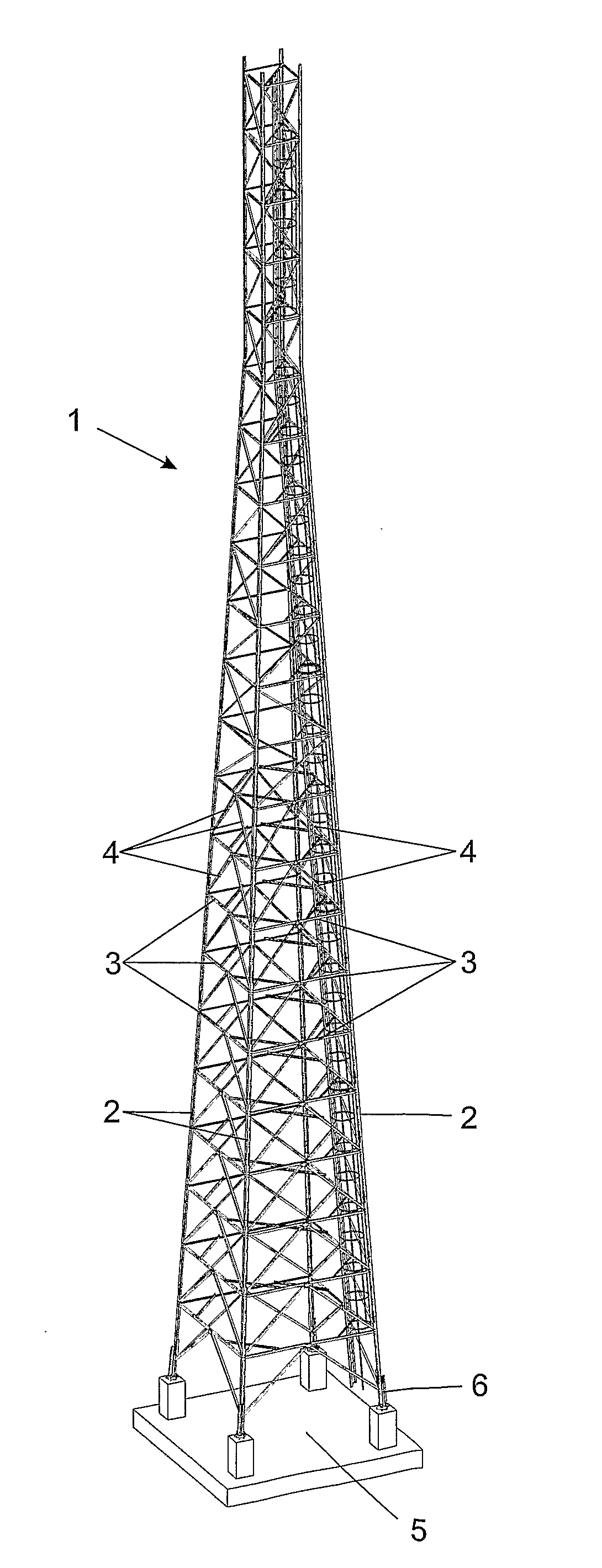
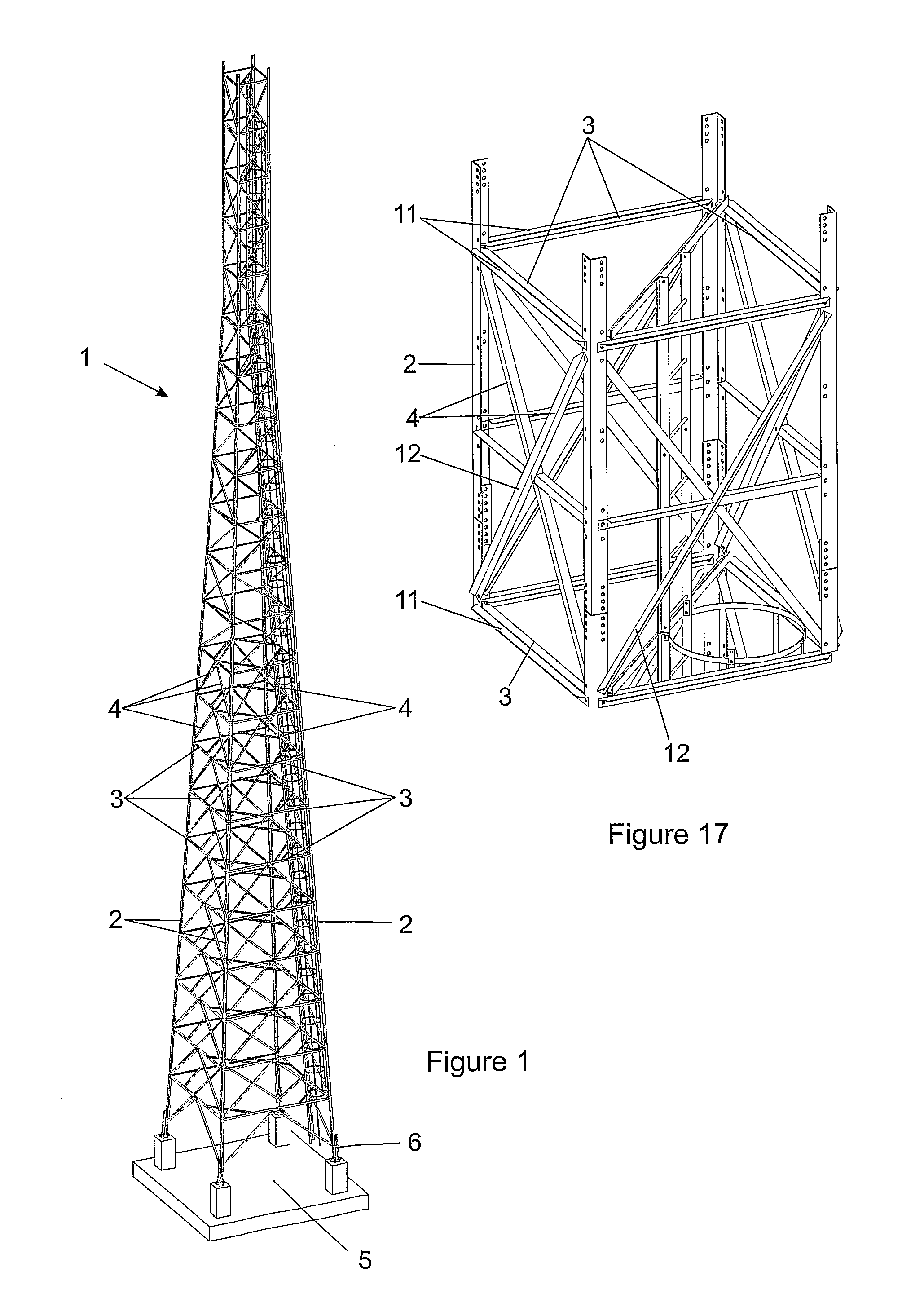
A lattice tower (1) is provided comprising generally upright leg elements that are arranged in plan view at the corners of a polygon with horizontal struts and diagonal braces interconnecting the leg elements. The lattice tower has a first arrangement of basic leg elements (2), basic horizontal struts (3) and basic diagonal braces (4) providing a first and basic predetermined load carrying capacity of the tower. Selected basic leg elements and / or basic horizontal struts and / or basic diagonal braces are provided with attachment formations whereby additional leg elements (10) and / or additional horizontal struts (7) and / or additional diagonal braces (8) may be secured to the basic leg elements and / or basic horizontal struts and / or basic diagonal braces to provide an increased predetermined load carrying capacity of the lattice tower.

Description

FIELD OF THE INVENTION[0001]This invention relates to an upgradable lattice tower of the general type commonly used for supporting elevated loads that often assume the form of wireless transmission equipment, especially wireless transmitters and antenna. The principles of the invention are, however, also applicable to other lattice towers such as may be used for the purpose of supporting water tanks or the like, or any other elevated loads, and such lattice towers are intended to fall within the scope of this invention. The invention also relates to components of such lattice towers.[0002]It is to be understood that the term lattice tower as used in this specification is intended to mean a tower having a latticed framework type of structure typically comprising generally upright leg elements (that may converge somewhat over at least a generally lower part of the height of the tower) that are generally arranged in plan view at the corners of a polygon, most commonly a square or trian...

Claims


Application Information

Patent Timeline
Patent Type & Authority Applications(United States)
IPC IPC(8): E04H12/00
CPCE04H12/10H01Q1/1207
Inventor HEDINGER, JOHANNORTJÉ, JOHANNES CORNELIUS
Owner HEDINGER JOHAN
Learn More